Coal bed underground gasifying method

An underground gasification and coal seam technology, applied in coal gasification, underground mining, construction, etc., can solve problems such as reducing operating pressure, and achieve the effect of increasing the generation rate and increasing the reaction contact surface.

Active Publication Date: 2015-01-28
ENN SCI & TECH DEV
View PDF7 Cites 7 Cited by
  • Summary
  • Abstract
  • Description
  • Claims
  • Application Information

AI Technical Summary

Problems solved by technology

However, the coal seam gap increase in the prior art can only expand the original coal seam cracks through high-pressure gas, because the operating pressure in the normal gasification stage is far lower than the pressure in the gap increase stage, so when turning from the gap increase stage to gasification After the gasification stage, the operating pressure will be greatly reduced, and the coal seam fissures that have been opened in the original coal seam will gradually close as the pressure decreases. The real impact on the gasification stage is very small, and it can only play a certain role in the ignition of the gap increase stage. effect

Method used


Image

  • Coal bed underground gasifying method
  • Coal bed underground gasifying method
  • Coal bed underground gasifying method

Examples


no. 1 example

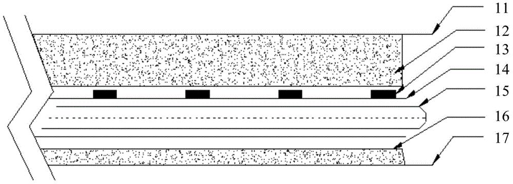
[0022] See figure 1 , which is a schematic diagram of the implementation of the directional drilling underground coal seam gasification in the first embodiment of the present invention. Such as figure 1 Shown:

[0023] A plurality of explosive devices 13 independent of each other are arranged in the coal seam gasification channel 16 that has been constructed in the coal seam 12 to be gasified. The gasification channel 16 is formed between the coal seam top plate 11 and the coal seam bottom plate 17. In this embodiment, the gasification The channel 16 is directional drilling. According to the installation positions of multiple explosive devices 13, the coal seam 12 to be gasified is divided into multiple coal seam sections (not shown in the figure), and the multiple explosive devices 13 correspond to each coal seam section respectively. In addition, the explosion influence radius of each explosion device 13 is preferably the distance from the coal seam roof 11 , and the expl...

no. 2 example

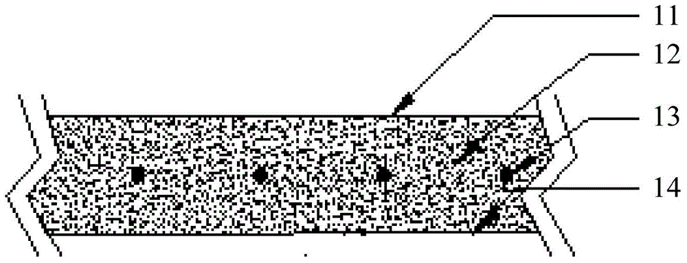
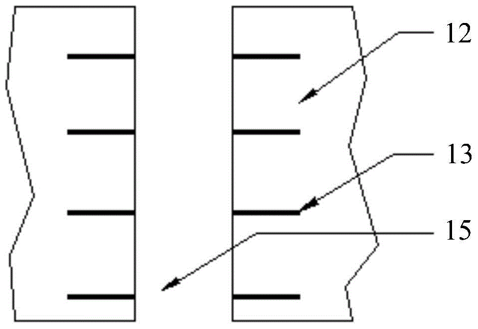
[0028] See Figure 2a and 2b , which is a schematic diagram of the way to realize underground gasification of tunnel-type well coal seams according to the second embodiment of the present invention. as shown in picture 2:

[0029] In tunnel-type well coal seam gasification, multiple explosive devices 13 are arranged in the coal seam 12 to be gasified, and each explosive device 13 is buried in the coal seam between the coal seam roof 11 and the coal seam floor 14 . The explosion influence radius of each explosion device 13 is preferably the distance from the coal seam roof 11 , and the explosion influence diameter is preferably the distance between each explosion device 13 . By increasing the thickness of the two ends of the buried explosive device 13, it will not be blasted when it explodes. After the explosion device 13 is arranged, the gap between it and the coal seam 12 to be gasified is sealed.

[0030] After that, it can be done like figure 1 As shown, a support pipe...


PUM


Abstract

The invention relates to a coal bed underground gasifying method. The coal bed underground gasifying method comprises the following steps of establishing a gasifying tunnel in a to-be-gasified coal bed; arranging a plurality of blasting devices in the to-be-gasified coal bed, wherein the blasting devices are arranged corresponding to a plurality of coal bed sections of the to-be-gasified coal bed; igniting or striking a fire in the gasifying tunnel to start the gasifying process; utilizing a flame movement heating method to gradually blast the blasting devices, so as to loosen the coal bed sections before the corresponding coal bed section is gasified. The coal bed underground gasifying method has the advantages that the blasting devices are pre-arranged in the to-be-gasified coal bed, so while cracks in the coal bed are increased by blasting, and the gasifying is also performed; before the gasifying of each coal bed section, the looseness of the corresponding coal bed section is completed, and the gasifying efficiency is improved.

Description

technical field [0001] The invention relates to the technical field of coal seam gasification, in particular to an underground coal seam gasification method. Background technique [0002] Underground coal gasification is carried out in the coal seam in the gasification channel. Its core technology is to make the gasification agent (air or oxygen, water vapor, etc.) fully contact with the underground coal seam, and through the pyrolysis and chemical action of coal, produce flammable gas. Therefore, the depth of the gasification reaction is an extremely important parameter, especially for diagenetic coals such as anthracite, lean coal, and lean coal, and coals with a high degree of carbonization, which sometimes only occur on the surface of the coal wall, which is not conducive to the gasification of underground coal mining. use. [0003] During the gasification process, the coal seam fracture rate (the degree of development of bedding, joints and fissures) directly affects ...

Claims


Application Information

Patent Timeline
Patent Type & Authority Applications(China)
IPC IPC(8): E21B43/295
CPCE21B43/295
Inventor 桂谢文
Owner ENN SCI & TECH DEV
Why Eureka
Try Eureka