LED module employing vacuum phase change technology and applicable to LED lighting

An LED module and LED lighting technology, applied in the field of lighting, can solve the problems of lack of super-power radiators, luminous spectrum drift, and shortened lifespan.

Inactive Publication Date: 2015-01-28
SHANGHAI LANGTAO OPTOELECTRONICS TECH CO LTD
View PDF4 Cites 2 Cited by
  • Summary
  • Abstract
  • Description
  • Claims
  • Application Information

AI Technical Summary

Problems solved by technology

[0005] However, the rise of the LED junction temperature will lead to a decrease in luminous efficiency, a shortened lifespan, a shift in the luminous spectrum, and in severe cases, the chip will be burned. Therefore, heat dissipation is one of the key problems that need to be solved in high-power LED lighting.
[0006] Most of the heat sinks for hi

Method used


Image

  • LED module employing vacuum phase change technology and applicable to LED lighting
  • LED module employing vacuum phase change technology and applicable to LED lighting
  • LED module employing vacuum phase change technology and applicable to LED lighting

Examples


Embodiment Construction

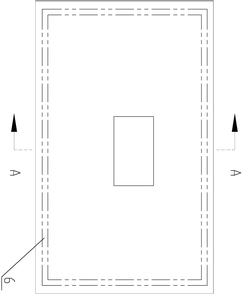
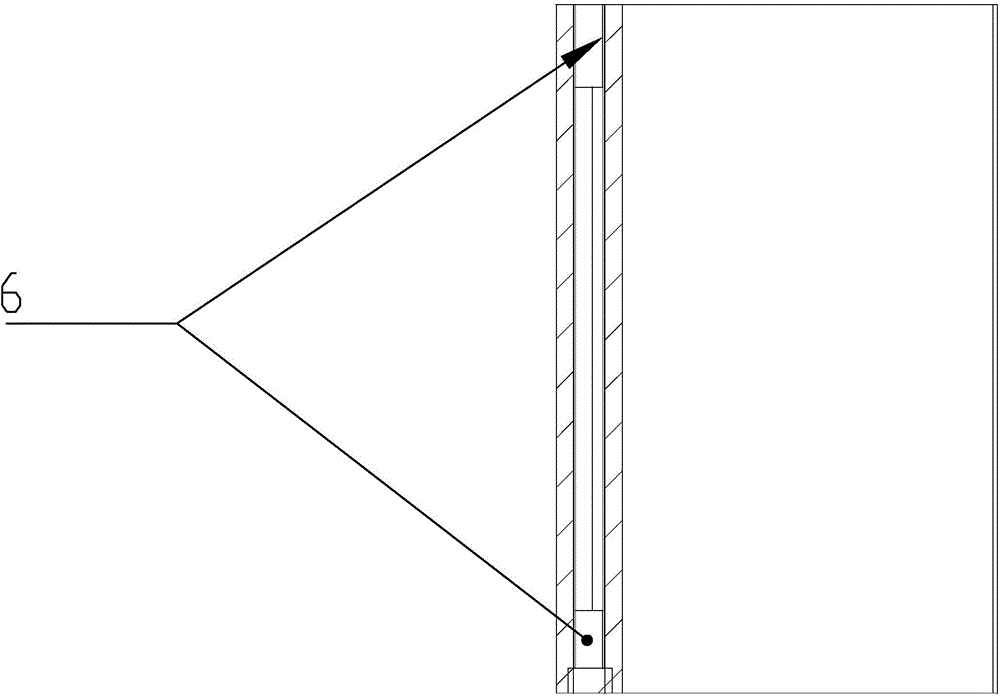
[0016] Such as figure 1 , figure 2 , image 3 As shown, the vacuum phase change technology LED module for LED lighting includes a radiator 1 and fins 2 on the LED light source 8, the radiator is a bottom plate 4 with a vacuum cavity 3 inside, and the vacuum cavity is filled with There is an ultra-low temperature medium 5; a narrow tube channel 6 is arranged in the vacuum chamber, and the narrow tube channel is a hollow tube around the vacuum chamber; a micro-groove group structure 7 is arranged on the surrounding wall of the vacuum chamber, that is, a wave-shaped slot hole 7- 1 connected groove line structure;

[0017] The boiling point of the ultra-low temperature medium is 13°C, and the vacuum strength is greater than 10 -2 support.

[0018] This module adopts vacuum phase change technology to realize rapid heat conduction and heat dissipation of the module, so as to realize the advantages of long life and low cost of the light source module. This module is compatible...


PUM

PropertyMeasurementUnit
Boiling pointaaaaaaaaaa

Abstract

An LED module employing vacuum phase change technology and applicable to LED lighting is mainly technically characterized in that a radiator is a bottom plate internally provided with a vacuum cavity filled with a cryogenic medium, the vacuum cavity is internally provided with a narrow-tube passage which is a hollow tube surrounding the vacuum cavity, and the peripheral wall of the vacuum cavity is provided with a micro-groove structure, namely corrugated grooves are connected into a groove-line structure. The LED module is in the overall vacuum sealed structure with the surrounding radiating fins, a principle of heat conduction of thermal tubes is generated, heat conduction and heat dissipation is more efficient than that of the thermal tubes, and heat conduction and heat dissipation are improved. The LED module with the special structure has the advantages that the cooling medium can quick gasify at low temperature to allow quick start of heat dissipation; the cooling medium is used with a new cooling medium, gasifying temperature is greatly lowered, heat dissipation speed is increased, and intermediate and marginal thermal gradient is decreased.

Description

technical field [0001] The invention relates to an LED module in the lighting field. Background technique [0002] LED modules are composed of radiators, LED light sources, lenses, sealing components, power supplies, etc. to form a single unit. LED lighting products use one or several modules to make different products. [0003] At present, there are mainly two types of modules used in LED lighting. One is a module that uses a single 1W-3W LED light source. Mature. However, there are disadvantages such as the low power of a single module, and the large size and heavy weight of the lamps when making larger power lighting lamps. [0004] The second is the module made of high-power LED COB light source. Since the manufacture of high-power LED COB light source is developing towards high performance, integration and miniaturization, the power density of its chip can reach hundreds of W / cm2. The electro-optical conversion efficiency of high-power LED is about 30%, and about 70%...

Claims


Application Information

Patent Timeline
IPC IPC(8): F21V29/56F21V29/74F21Y101/02
CPCF21Y2101/00
Inventor 裘年儿
Owner SHANGHAI LANGTAO OPTOELECTRONICS TECH CO LTD
Why Eureka
Try Eureka