
Spiral condenser and manufacturing process of spiral condenser

A condenser and spiral technology, which is applied in the field of spiral condensers and its manufacturing process, can solve the problems of multiple manufacturing processes, poor heat dissipation performance, and damaged tubes, and achieve the effects of simple process, reduced manufacturing difficulty, and reduced labor intensity

Inactive Publication Date: 2015-01-28
CHANGZHOU CHANGZHENG HEAT EXCHANGER TECH
View PDF8 Cites 14 Cited by
  • Summary
  • Abstract
  • Description
  • Claims
  • Application Information

AI Technical Summary

Problems solved by technology

[0002] Existing condensers generally use water condensers, longitudinal mixing tube bundle condensers, wire tube condensers, etc. In order to exert a better cooling effect, existing condensers generally have the characteristics of large heat dissipation area, which results in One defect is that the volume is large, resulting in high cost, and the application is greatly restricted; and once a small-volume condenser is used, there will be a defect of poor heat dissipation; and in the production of the condenser, the existing technology has The production process of the condenser is many and complicated, and the production is relatively difficult. Generally, the tube and the fin are connected by three-way welding, so there is a hidden danger of damaging the tube, causing pipeline leakage, picking up the cooling effect, and losing in terms of cost. also very big

Method used


Image

  • Spiral condenser and manufacturing process of spiral condenser
  • Spiral condenser and manufacturing process of spiral condenser
  • Spiral condenser and manufacturing process of spiral condenser

Examples


Embodiment Construction

[0033] The present invention will be further described below in conjunction with the accompanying drawings and specific embodiments.

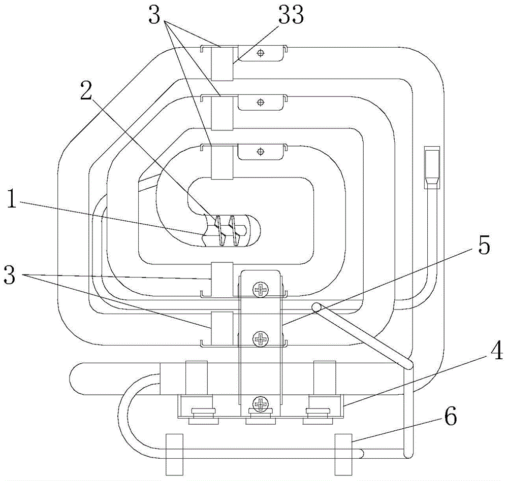
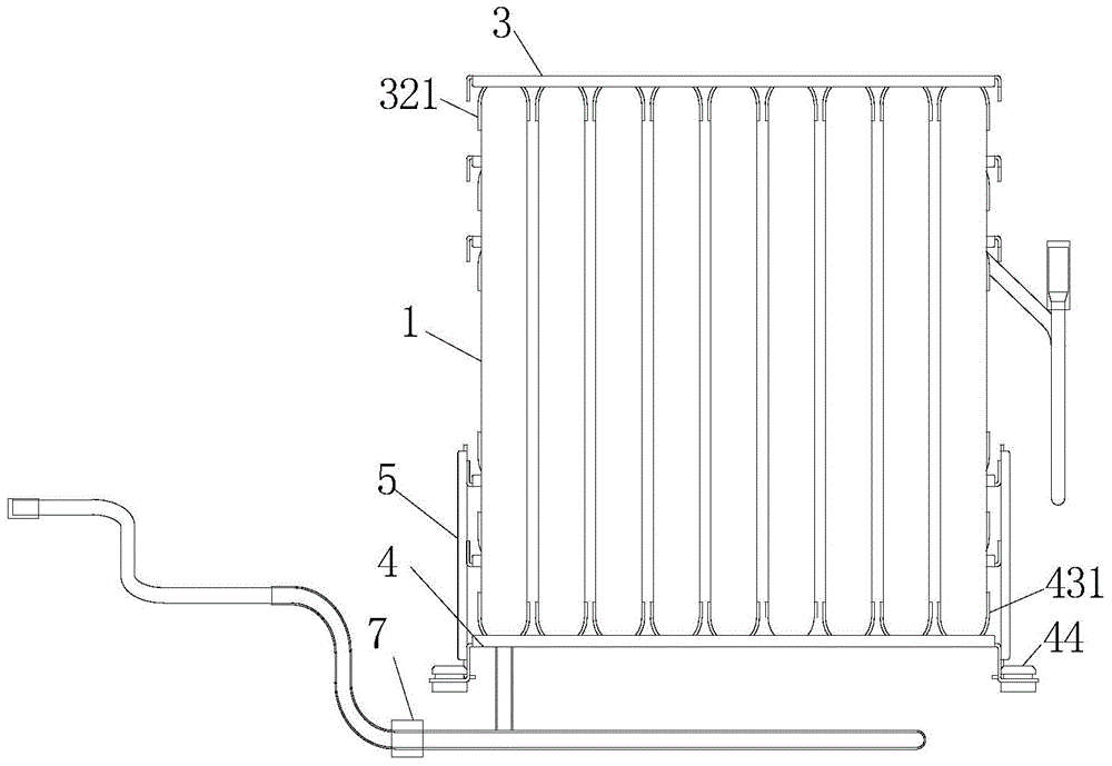
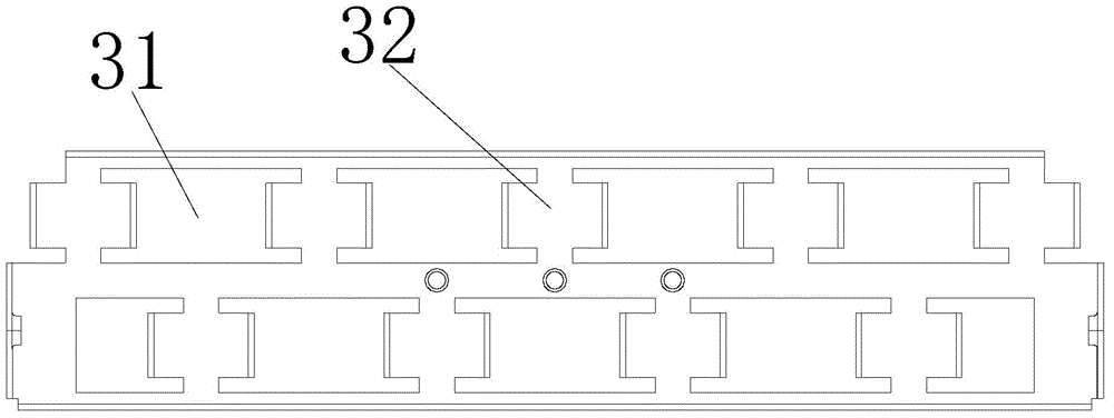
[0034] Such as Figure 1 to Figure 8 , a spiral condenser, including a heat dissipation pipe 1 and fins 2, the heat dissipation pipe 1 is bent and wound to form a cuboid structure composed of multi-layer circuitous heat dissipation pipe units, the heat dissipation pipe units are parallel to each other, and the heat dissipation The spacing between the tube units is the same and set to 10mm-30mm, generally set to 10mm, 15mm, 20mm, 25mm, the fins 2 are spirally wound on the outer surface of the heat pipe 1, and the fins are set as straight fins Type structure, the spacing between adjacent fins 2 is set to 4mm-10mm, generally set to 5mm, 6mm, 7mm, 8mm; also includes a bracket for supporting and fixing the cuboid structure composed of multi-layer circuitous heat pipe units components.

[0035]The connection between the inside of the fin 2 and the ...


PUM

PropertyMeasurementUnit
Thicknessaaaaaaaaaa

Abstract

The invention relates to a spiral condenser, which comprises a heat radiation pipe and fins, wherein the heat radiation pipe forms a cuboid structure through bending and winding, the cuboid structure consists of a plurality of layers of circuitous heat radiation pipe units, the heat radiation pipe units are mutually parallel, in addition, the gap between the heat radiation pipe units is set to be 10mm to 30mm, the fins are spirally arranged on the outer surface of the heat radiation pipe in a winding way and are of a straight sheet type structure, the gap between the adjacent fin blades is set to be 4mm to 10mm, the spiral condenser also comprises a support frame assembly used for supporting and fixing the cuboid structure consisting of the layers of circuitous heat radiation pipe units. The spiral condenser has the characteristics that the cost is low, the manufacturing is simple, the heat radiation effect is good, the refrigeration is fast, and the like.

Description

technical field [0001] The invention relates to the technical field of refrigeration, in particular to a spiral condenser and a manufacturing process thereof. Background technique [0002] Existing condensers generally use water condensers, longitudinal mixing tube bundle condensers, wire tube condensers, etc. In order to exert a better cooling effect, existing condensers generally have the characteristics of large heat dissipation area, which results in One defect is that the volume is large, resulting in high cost, and the application is greatly restricted; and once a small-volume condenser is used, there will be a defect of poor heat dissipation; and in the production of the condenser, the existing technology has The production process of the current condenser is many and complicated, and the production is relatively difficult. Generally, the tube and the fin are connected by three-way welding, so there is a hidden danger of damaging the tube, causing pipeline leakage, pi...

Claims


Application Information

Patent Timeline
IPC IPC(8): F25B39/04F28F1/36F28F9/013
CPCF25B39/04F28F1/36F28F9/0137
Inventor 郑磊郑文伟陈建元陆海华谭长新
Owner CHANGZHOU CHANGZHENG HEAT EXCHANGER TECH
Learn More