Continuous wave power probe

A wave power and microwave technology, applied in the field of continuous wave power probes, can solve the problems of small detection circuit area, high requirements, poor detection output consistency, etc., to achieve good linearity and frequency response characteristics consistency, high detection balance, The effect of eliminating the potential difference

Active Publication Date: 2015-01-28
CHINA ELECTRONIS TECH INSTR CO LTD
View PDF7 Cites 6 Cited by
  • Summary
  • Abstract
  • Description
  • Claims
  • Application Information

AI Technical Summary

Problems solved by technology

[0005] (1) The area of ​​the detection circuit is small, and the requirements for the welding of the device are very high. There are great problems in the welding of the device. For example, the welding position of the double detection diode is not completely symmetrical, which will cause poor detection balance; different metal connections will form a large potential difference ; Poor detection balance and potential difference will affect the accuracy of the power sensor for small power measurement
[0006] (2) The diode detection circuit is designed with separate components, and the consistency of the detection output is poor, especially the linearity and frequency response characteristics of the detection output. Even if the power probes of the same batch have a large gap
[0007] (3) Due to the small area of ​​the detection circuit and the short microstrip line, if the operation is not standardized or the temperature is too high during the welding process, it is easy to damage the microstrip line of the detection circuit, resulting in a certain number of defective products

Method used


Image

  • Continuous wave power probe

Examples


Embodiment Construction

[0059] The following will clearly and completely describe the technical solutions in the embodiments of the present invention with reference to the accompanying drawings in the embodiments of the present invention. Obviously, the described embodiments are only some, not all, embodiments of the present invention. Based on the embodiments of the present invention, all other embodiments obtained by persons of ordinary skill in the art without making creative efforts belong to the protection scope of the present invention.

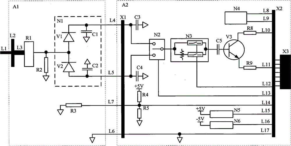
[0060] like figure 1 As shown, the continuous wave power probe of the present invention includes two parts: a microwave detection circuit A1 and a large dynamic range detection voltage processing circuit A2, wherein the microwave detection circuit A1 is placed on a gallium arsenide substrate and sealed inside a cavity ; Large dynamic range detection voltage processing circuit A2 is located in the printed board made of RF4 and sealed by a metal shell.

[0061] T...


PUM


Abstract

The invention provides a continuous wave power probe, comprising a microwave detection circuit A1 and a large dynamic range detection voltage processing circuit A2, wherein the microwave detection circuit A1 is positioned on a gallium arsenide substrate and sealed in a cavity, and the large dynamic range detection voltage processing circuit A2 is positioned in a printed circuit board and sealed by a metal shell. The continuous wave power probe based on MMIC technology and with the dynamic range of 90 dB, provided by the invention, is connected to a continuous wave power meter host by a cable, thus achieving that the dynamic range of the single probe with the frequency range of 10MHz-18GHz reaches 90dB, and also achieving accurate measurement of the continuous wave power.

Description

technical field [0001] The invention relates to the technical field of testing, in particular to a continuous wave power probe. Background technique [0002] Power is one of the most basic and important parameters of microwave signals. The development and production of almost all electronic equipment and electronic components requires a power meter for power testing. The microwave power sensor is the core component of the microwave power meter, and the performance of the microwave power sensor determines the core index of the microwave power meter. [0003] The existing microwave power probe is to design a small microstrip circuit on a gallium arsenide substrate. Two pieces of Schottky diodes and detection capacitors are symmetrically welded on the microstrip circuit, and the microstrip circuit is sealed in a cavity with a small space. body interior. [0004] Existing microwave power sensors have the following disadvantages: [0005] (1) The area of ​​the detection circui...

Claims


Application Information

Patent Timeline
Patent Type & Authority Applications(China)
IPC IPC(8): G01R21/00
Inventor 李金山冷朋赵浩李强徐达旺董占勇刘元商
Owner CHINA ELECTRONIS TECH INSTR CO LTD
Why Eureka
Try Eureka