Double-layer annular truss antenna mechanism based on passive drive

A ring truss and antenna technology, which is applied in the field of double-layer ring truss-type deployable antenna mechanism, can solve the problems of easy entanglement and deployment reliability of cables, failure to meet rigidity requirements, and complex drive structure, etc., and achieve light weight and weight reduction , Expand the simple effect of movement

Active Publication Date: 2015-01-28
HARBIN INST OF TECH
View PDF3 Cites 15 Cited by
  • Summary
  • Abstract
  • Description
  • Claims
  • Application Information

AI Technical Summary

Problems solved by technology

[0004] The present invention is to solve the problem that the existing large-diameter single-ring annular truss antenna has low rigidity and cannot meet the requirement of rigidity in use, and the driving structure of the existing annular truss antenna mechanism is complicated, the weight is large, and the deployment of the cable is easy to cause winding and deployment reliability. lower problem, and then provide a passively driven double-layer ring truss antenna mechanism

Method used


Image

  • Double-layer annular truss antenna mechanism based on passive drive
  • Double-layer annular truss antenna mechanism based on passive drive
  • Double-layer annular truss antenna mechanism based on passive drive

Examples


specific Embodiment approach 1

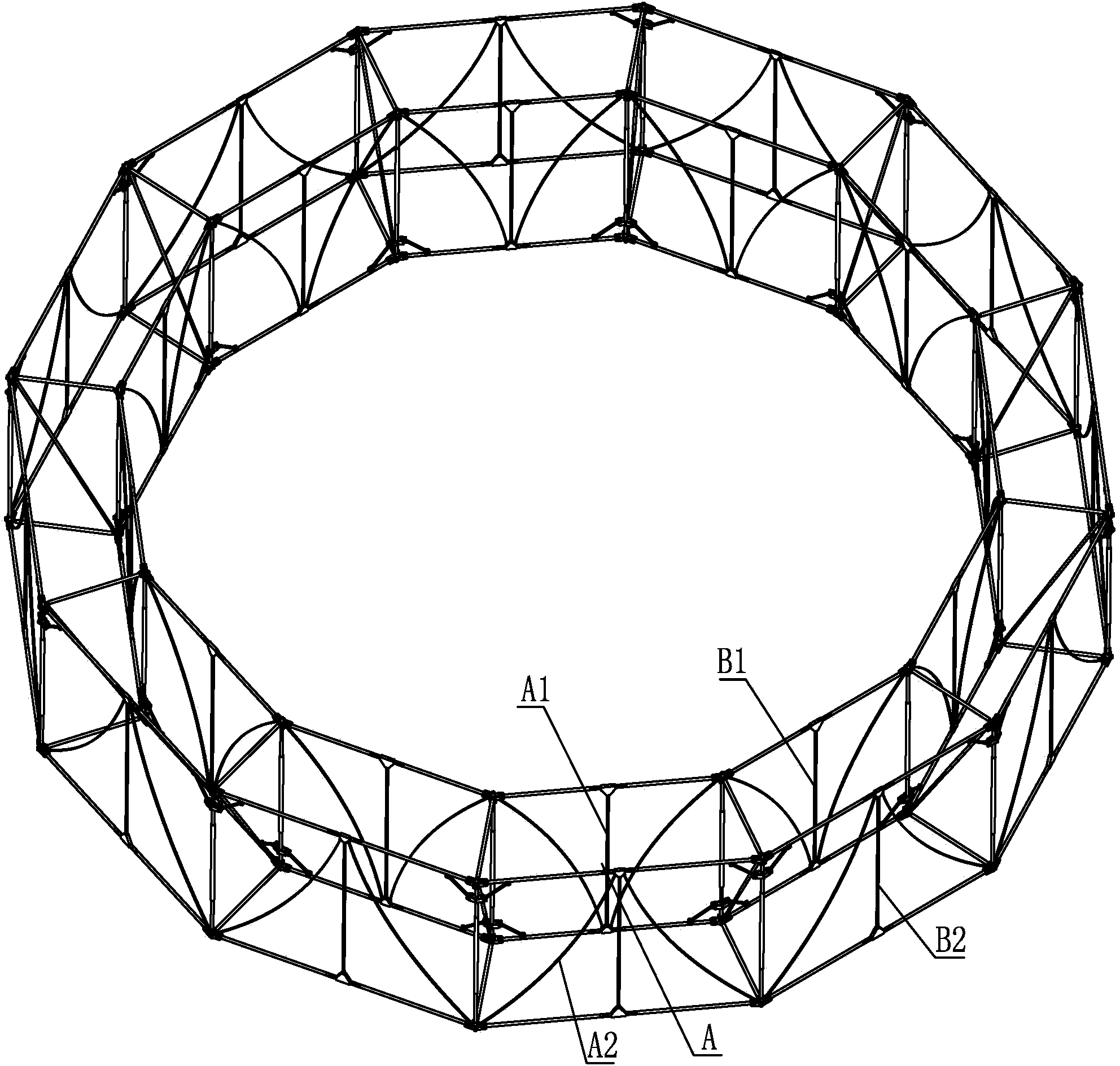
[0024] Specific implementation mode one: combine Figure 1-Figure 13 Explain that the passively driven double-layer ring truss antenna mechanism of this embodiment includes a plurality of inner and outer truss-type foldable unit modules A, a plurality of inner transitional folding components B1 and a plurality of outer transitional folding components B2;

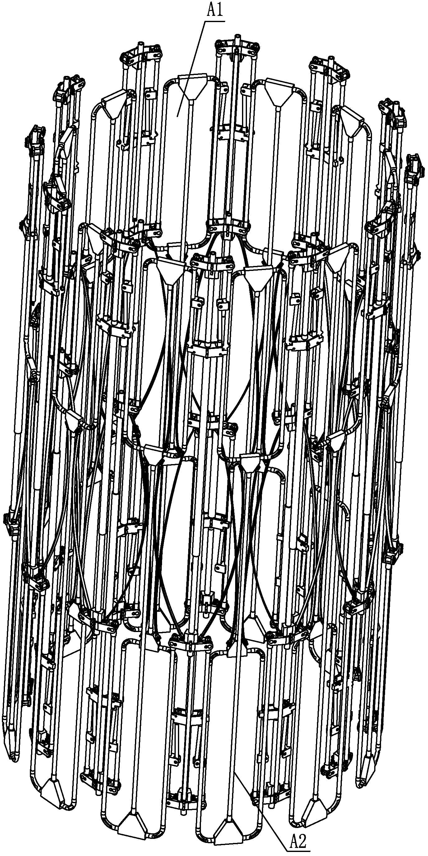
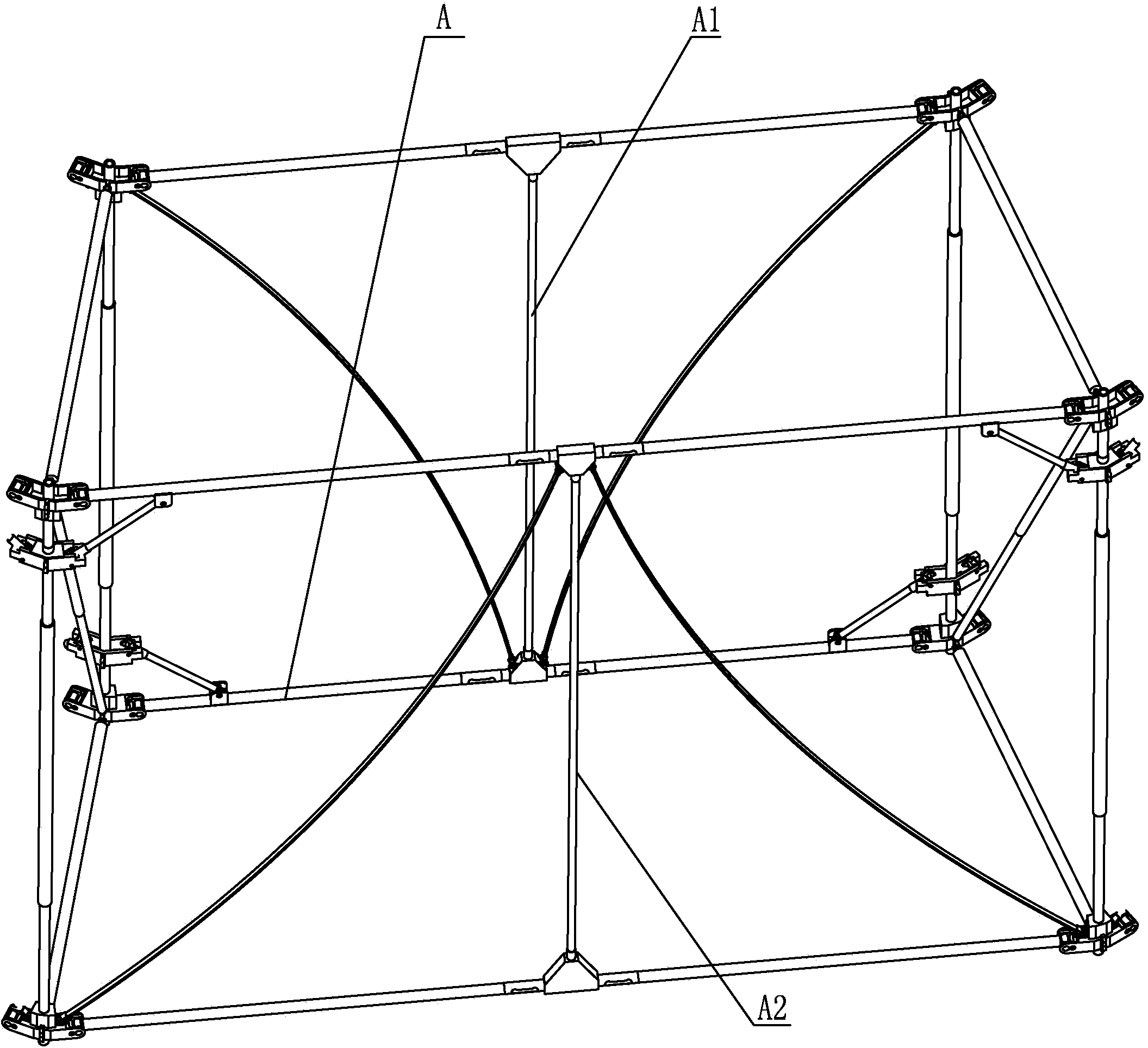
[0025] Each inner and outer truss type foldable unit module A includes an inner foldable unit module A1, an outer foldable unit module A2 and two inner and outer connecting truss assemblies 3;

[0026] The inner folding unit module A1 includes a central connecting vertical rod 5, an upper connecting joint 9, a lower connecting joint 14, two inner upper chords 7, two inner lower chords 16, two inner supporting elastic rods 4, two cranks 10, Two sliders 11, two inner support vertical bars 13, four self-locking hinges 6 and four chords expand and drive elastic hinges 15;

[0027] The upper and lower ends of the two inner suppo...

specific Embodiment approach 2

[0034] Specific implementation mode two: combination Figure 4 , Figure 5 , Figure 7 and Figure 8 Explain that the inner transitional folding assembly B1 of this embodiment includes a central connecting vertical rod 5, an upper connecting joint 9, a lower connecting joint 14, two transitional inner supporting elastic rods 51, two transitional inner upper chords 31, two transitional inner The lower chord 32, the two cranks 10 and the four chords expand to drive the elastic hinge 15; between the upper connecting joint 9 and the lower connecting joint 14, a central connecting vertical bar 5 connected with the two is arranged, and two transition inner upper chords 31 coaxial arrangement, the two transition inner lower chords 32 are coaxially arranged, and the two transition inner upper chords 31 are arranged above the two transition inner lower chords 32;

[0035] The two ends of the upper connection joint 9 are respectively connected to a transition inner upper chord 31 thr...

specific Embodiment approach 3

[0039] Specific implementation mode three: combination Figure 4 , Figure 5 and Figure 9 Explain that each of the internal and external connecting truss assemblies 3 in this embodiment includes an upper cross bar 28, a lower cross bar 29, a diagonal upper chord 18, a diagonal lower chord 20, and a chord expansion driving elastic hinge 15;

[0040] Between the diagonal upper chord 18 and the diagonal lower chord 20 is arranged a chord fixedly connected with the two to expand and drive the elastic hinge 15, the upper cross bar 28, the lower cross bar 29, the diagonal upper chord 18, and the diagonal lower chord 20 The elastic hinges 15 driven by the chords are arranged in a Z shape, the diagonal upper chord 18 is hinged with the self-locking hinge 6 on the outer folding unit module A2, and the diagonal lower chord 20 is connected with the self-locking hinge on the inner folding unit module A1 6 are hinged, and the upper cross bar 28 and the lower cross bar 29 are hinged betw...


PUM


Abstract

The invention provides a double-layer annular truss antenna mechanism based on passive drive and relates to double-layer annular truss type expandable antenna mechanisms. The problems that an existing large-caliber single-ring annular truss antenna is small in rigidity, the use rigidity requirement can not be met, an existing annular truss antenna mechanism is complex in drive structure and large in weight, inhaul cables are prone to be twisted after being used for unfolding the mechanism, and the unfolding reliability is low are solved. The double-layer annular truss antenna mechanism comprises multiple inner and outer truss foldable unit modules, multiple inner transition folding assemblies and multiple outer transition folding assemblies. Each inner and outer truss foldable unit module comprises an inner folding unit module, an outer folding unit module and two inner and outer connection truss assemblies. Inner supporting vertical rods and outer supporting vertical rods which are opposite are connected through the inner and outer connection truss assemblies. After the inner and outer truss foldable unit modules are unfolded, an inner and outer double-layer annular truss polyhedron is formed. The double-layer annular truss antenna mechanism is used for a satellite, a space station and a space probe.

Description

technical field [0001] The invention relates to a double-layer annular truss type expandable antenna mechanism, which belongs to the technical field of aerospace equipment and equipment. Background technique [0002] With the development of technology and the promotion of applications, in the fields of satellite communication, wireless broadcasting system, earth observation, land remote sensing, deep space exploration and deep space communication, space-borne large-scale deployable antennas have been widely used in navigation satellites, communication satellites, etc. , relay satellites, meteorological satellites and reconnaissance satellites. In order to meet the needs of multi-function, multi-band, large capacity, high power, and long life, satellite antennas are required to have large diameter, high precision, light weight, and high rigidity. However, due to the limitation of the rocket's effective carrying space and carrying capacity , the antenna is required to be fold...

Claims


Application Information

Patent Timeline
Patent Type & Authority Applications(China)
IPC IPC(8): H01Q1/10
Inventor 郭宏伟刘荣强史创邓宗全
Owner HARBIN INST OF TECH
Why Eureka
Try Eureka