Supercharge Your Innovation With Domain-Expert AI Agents!

A digital output buffer and its control method

A digital output and control method technology, applied in the direction of logic circuit connection/interface layout, etc., can solve the problem of high power consumption of the output buffer, and achieve the effects of reducing power consumption, strong anti-interference ability, and avoiding circuit noise

Active Publication Date: 2017-04-26
SILICON STAR TECH
View PDF5 Cites 0 Cited by
  • Summary
  • Abstract
  • Description
  • Claims
  • Application Information

AI Technical Summary

Problems solved by technology

The downside is that the output buffer consumes a large

Method used


Image

  • A digital output buffer and its control method
  • A digital output buffer and its control method
  • A digital output buffer and its control method

Examples


Embodiment

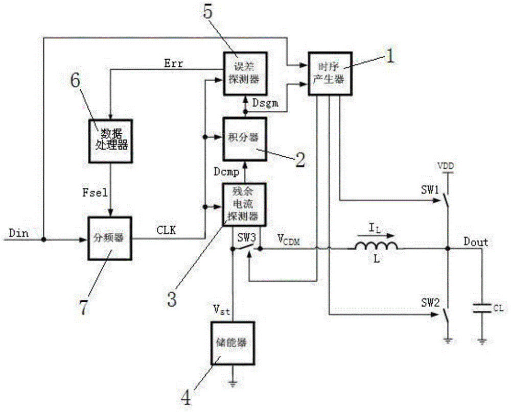
[0037] Embodiment: a kind of digital output buffer of the present invention, as figure 1 As shown, it includes a timing generator 1, an integrator 2, a residual current detector 3, an energy storage device 4, an error detector 5, a data processor 6, a frequency divider 7, an inductor L, a load capacitor CL, and a first switching tube SW1, the second switching tube SW2 and the third switching tube SW3, one end of the energy storage device 4 is grounded, the other end of the energy storage device 4 is electrically connected to the first conduction end of the third switching tube SW3, and the second end of the third switching tube SW3 The conduction end is electrically connected to one end of the inductance L, and the other end of the inductance L is electrically connected to the upper plate of the load capacitor CL, the first conduction end of the first switch tube SW1, and the first conduction end of the second switch tube SW2, and the capacitor The lower plate of CL and the se...


PUM


Abstract

A digital output buffer and the control method therefor are disclosed. The digital output buffer includes a timing generator(1), an integrator(2), a residual current detector(3), an energy storage device(4), an inductor L, a load capacitor CL, a first transistor SW1, a second transistor SW2 and a third transistor SW3. The energy storage device(4), the inductor L, the load capacitor CL, the first transistor SW1, the second transistor SW2 and the third transistor SW3 constitute the main circuit of the digital output buffer, and the integrator(2) and the residual current detector(3) constitute the negative feedback circuit of the digital output buffer. Thereby, the power consumption of the digital output buffer can be effectively reduced.

Description

technical field [0001] The invention relates to the technical field of output buffers, in particular to a digital output buffer and a control method thereof. Background technique [0002] As the frequency of digital signals increases, the digital output buffer consumes a lot of power when output buffering the data. Therefore, it is necessary to design a digital output buffer that reduces power consumption. [0003] Chinese Patent Publication No. CN103269217, published on August 28, 2013, the name of the invention is output buffer, the application discloses an output buffer, which includes first and second transistors and a self-bias circuit, the first The transistor has a control electrode, an input electrode coupled to the output terminal, and an output electrode. The second transistor has a control electrode, an input electrode coupled to the output electrode of the first transistor, and an output electrode coupled to a reference voltage. The self-bias circuit is coupled ...

Claims


Application Information

Patent Timeline
Patent Type & Authority Patents(China)
IPC IPC(8): H03K19/0175
CPCH03K19/0175
Inventor 陈锋
Owner SILICON STAR TECH
Features
  • R&D
  • Intellectual Property
  • Life Sciences
  • Materials
  • Tech Scout
  • Unparalleled Data Quality
  • Higher Quality Content
  • 60% Fewer Hallucinations
Learn More