Unlock instant, AI-driven research and patent intelligence for your innovation.

Delay phase-locked loop (DLL) and duty ratio rectification circuit (DCC) structure

A technology of delay phase-locked loop and circuit structure, applied in the direction of electrical components, automatic power control, etc., can solve the problem of inaccurate output duty cycle, and achieve the effect of improving the duty cycle

Inactive Publication Date: 2015-01-28
XI AN UNIIC SEMICON CO LTD
View PDF5 Cites 2 Cited by
  • Summary
  • Abstract
  • Description
  • Claims
  • Application Information

AI Technical Summary

Problems solved by technology

[0013] In order to solve the technical problem that the existing DLL and DCC circuits are limited by the minimum input pulse, or the output duty cycle cannot be accurate to 50%, the invention provides a delay-locked loop and a duty cycle correction circuit

Method used


Image

  • Delay phase-locked loop (DLL) and duty ratio rectification circuit (DCC) structure
  • Delay phase-locked loop (DLL) and duty ratio rectification circuit (DCC) structure
  • Delay phase-locked loop (DLL) and duty ratio rectification circuit (DCC) structure

Examples


Embodiment Construction

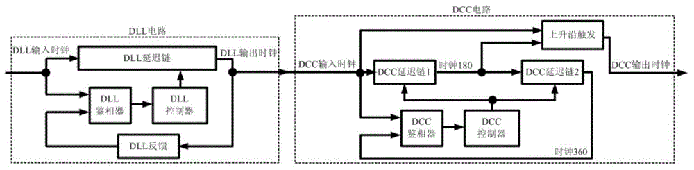
[0025] Such as image 3 As shown, the delay phase-locked loop and the duty ratio correction circuit of the present invention: first input the first duty ratio correction circuit DCC1 (hereinafter referred to as the DCC1 circuit), then through the delay phase locked loop DLL (hereinafter referred to as the DLL circuit), and finally through the The second duty cycle correction circuit DCC2 (hereinafter referred to as DCC2 circuit) outputs the final clock.

[0026] The first duty ratio correction circuit DCC1 includes a first DCC delay chain and a rising edge trigger, the output end of the first DCC delay chain is connected to the input end of the rising edge trigger, and the DCC input signal is simultaneously input to the first DCC delay chain and the rising edge trigger. Rising edge trigger;

[0027] The delay-locked loop DLL includes a DLL delay chain, a DLL phase detector, a DLL controller and a DLL feedback circuit. The output end of the DLL delay chain is connected to the ...


PUM


Abstract

The invention relates to a delay phase-locked loop (DLL) and duty ratio rectification circuit (DCC) structure. The DLL and DCC structure comprises a first DCC1, a DLL, a second CC2 and an inverter; the first DCC1 comprises a first DCC delay chain and a rising edge trigger; and the output end of the DLL is connected with the input end of a second DCC delay chain and the input end of a falling edge trigger. The DLL and DCC structure provided by the invention solves the technical problem that a conventional DLL and DCC is restricted by an input minimum pulse or an output duty ratio cannot be as accurate as 50%. According to the circuit provided by the invention, the time-delay chain transmission duty ratio distortion delta dll of a DLL circuit can be reduced by half, so that the duty ratio of the output clock of the whole circuit is greatly improved compared to the conventional DLL and DCC.

Description

technical field [0001] The invention relates to a delay-locked loop and a duty ratio correction circuit structure. Background technique [0002] Delay-locked loops (DLLs) and duty-cycle correction circuits (DCCs) are widely used in microprocessors, memory interfaces, interfaces between chips, and clock distribution networks in large-scale integrated circuits. The delay-locked loop DLL is used for clock synchronization to solve the problem of clock skew, so that the clock delay within the chip or between chips has enough margin, thereby improving the timing function of the system. The duty cycle correction circuit DCC is used to adjust the duty cycle of the clock (usually 50%), so that both the rising edge and the falling edge of the clock can be used for sampling data, thereby increasing the signal transmission rate. DLL and DCC are often used together in various application systems. [0003] DLL circuit working principle: DLL is composed of DLL delay chain, DLL phase dete...

Claims


Application Information

Patent Timeline
Patent Type & Authority Applications(China)
IPC IPC(8): H03L7/08
Inventor 亚历山大
Owner XI AN UNIIC SEMICON CO LTD
Features
  • R&D
  • Intellectual Property
  • Life Sciences
  • Materials
  • Tech Scout
  • Unparalleled Data Quality
  • Higher Quality Content
  • 60% Fewer Hallucinations
Learn More