Synchronizing signal zero-crossing-point positioning method and device

A technology of synchronous signal and positioning method, which is applied in the field of signal processing, can solve the problem of inaccurate positioning of the zero crossing point of the synchronous signal, and achieve the effect of solving inaccurate positioning and improving the success rate

Active Publication Date: 2015-01-28
BEIJING AIPUZHICHENG NETWORK TECH
View PDF6 Cites 10 Cited by
  • Summary
  • Abstract
  • Description
  • Claims
  • Application Information

AI Technical Summary

Problems solved by technology

[0007] The main purpose of the present invention is to provide a method and device for positioning the zero-crossing point of the synchronous signal to solve the problem of inaccurate positioning of the zero-crossing point of the synchronous signal in the prior art

Method used


Image

  • Synchronizing signal zero-crossing-point positioning method and device
  • Synchronizing signal zero-crossing-point positioning method and device
  • Synchronizing signal zero-crossing-point positioning method and device

Examples


Embodiment 1

[0030] According to the embodiment of the present invention, a method embodiment that can be implemented or executed by the device embodiment of the present application is provided. It should be noted that the steps shown in the flow chart of the accompanying drawings can be executed in a program such as a set of computer-executable instructions computer system, and although a logical order is shown in the flowcharts, in some cases the steps shown or described may be performed in an order different from that shown or described herein.

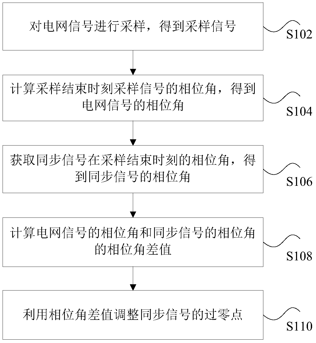
[0031] According to an embodiment of the present invention, a method for locating a zero-crossing point of a synchronous signal is provided. The method for locating a zero-crossing point of a synchronous signal provided by an embodiment of the present invention is described in detail below:

[0032] figure 1 is a flow chart of a positioning method for a synchronization signal zero-crossing point according to an embodiment of the present inventi...

Embodiment 2

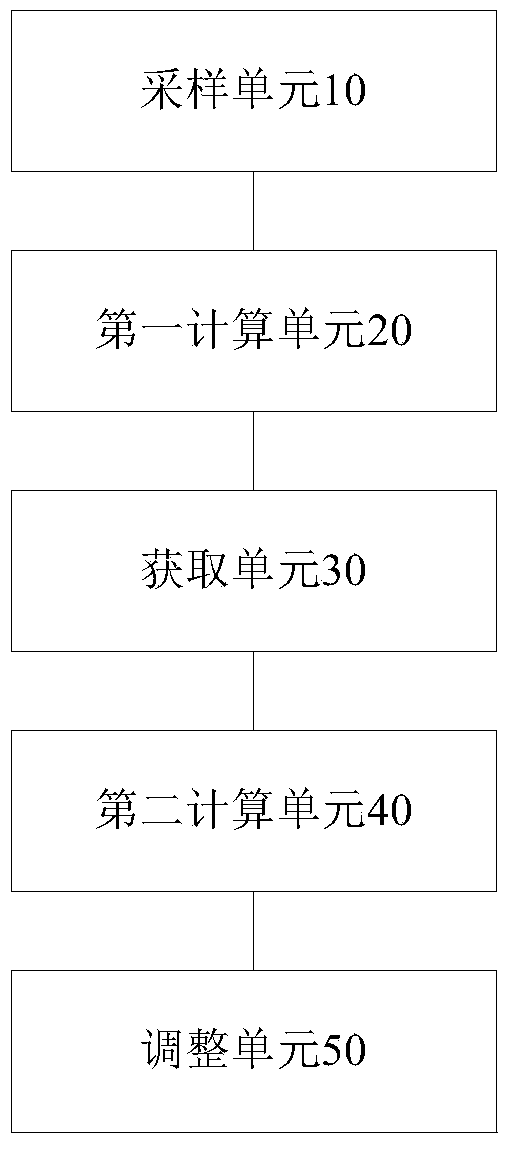
[0051] According to an embodiment of the present invention, there is also provided a synchronization signal zero-crossing point positioning device for implementing the above synchronization signal zero-crossing point positioning method, and the synchronization signal zero-crossing point positioning device is mainly used to implement the above content of the embodiment of the present invention The method for locating the zero-crossing point of the synchronous signal provided is as follows a specific introduction to the positioning device for the zero-crossing point of the synchronous signal provided by the embodiment of the present invention:

[0052] image 3 is a schematic diagram of a positioning device for a synchronization signal zero-crossing point according to an embodiment of the present invention, such as image 3 As shown, the positioning device for the zero-crossing point of the synchronization signal mainly includes a sampling unit 10, a first calculation unit 20, a...


PUM


Abstract

The invention discloses a synchronizing signal zero-crossing-point positioning method and device. The synchronizing signal zero-crossing-point positioning method comprises the steps of sampling a power grid signal to obtain a sampled signal; calculating a phase angle of the sampled signal at the sampling completion moment to obtain the phase angle of the sampled signal; obtaining a phase angle of a synchronizing signal at the sampling completion moment to obtain the phase angle of a synchronizing signal; calculating the difference value between the phase angle of the sampled signal and the phase angle of the synchronizing signal; utilizing the difference value of the phase angles to adjust a zero crossing point of the synchronizing signal. By means of the synchronizing signal zero-crossing-point positioning method and device, the problem that the position of a zero crossing point of a synchronizing signal in the prior art is inaccurate to position is solved, and further the effects of accurately positioning the position of the zero crossing point of the synchronizing signal and improving the carrier communication success rate of a power line network are achieved.

Description

technical field [0001] The invention relates to the field of signal processing, in particular to a positioning method and device for a zero-crossing point of a synchronous signal. Background technique [0002] The power line network is a widespread network, and it is very convenient to use it for communication. The application of power carrier communication in high-voltage transmission network is relatively successful. For low-voltage distribution network, due to the influence of impedance changes and multipath interference, the transmission of low-voltage power carrier signal will have obvious attenuation and distortion, and the change of power grid will seriously affect the communication. For the success rate, in order to improve its anti-jamming ability, one aspect is to increase its transmission distance, and the other is to improve the synchronization of its transmitted signals to ensure the effectiveness of signal transmission. [0003] In the process of improving the...

Claims


Application Information

Patent Timeline
Patent Type & Authority Applications(China)
IPC IPC(8): H04L7/00H04B3/54
Inventor 李雪伟王志明李敏智
Owner BEIJING AIPUZHICHENG NETWORK TECH
Why Eureka
Try Eureka