Chlorine dioxide gas generating device and sterilization box for medical equipment

A gas generating device, chlorine dioxide technology, applied in the direction of gas generating devices, chlorine dioxide, chlorine oxide, etc., can solve the problem of inability to generate chlorine dioxide gas in a long-term and stable manner, and achieve the effect of expanding the surface area

Inactive Publication Date: 2016-03-30
FM IWATE
View PDF6 Cites 2 Cited by
  • Summary
  • Abstract
  • Description
  • Claims
  • Application Information

AI Technical Summary

Problems solved by technology

On the other hand, since the lozenge body is used by dissolving it in water, especially at the beginning of use, a very high concentration of chlorine dioxide gas will be released, so there is a problem that the chlorine dioxide gas cannot be generated stably for a long time. Chlorine Oxide Gas Problems

Method used


Image

  • Chlorine dioxide gas generating device and sterilization box for medical equipment
  • Chlorine dioxide gas generating device and sterilization box for medical equipment
  • Chlorine dioxide gas generating device and sterilization box for medical equipment

Examples


Embodiment 1

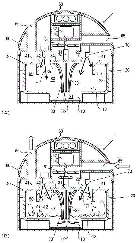
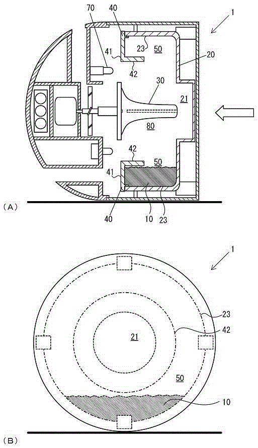
[0068] First, Example 1, see figure 1 and figure 2 The chlorine dioxide gas generator 1 having a surface area enlarging unit is described. The area enlarging unit is formed by a water droplet scatterer 30 having an open funnel shape above and a rotating mechanism that rotates the water droplet scatterer 30 around the central axis 31. composition. The chlorine dioxide gas generator 1 of Example 1 has a height of 15 cm, a size of 15 cm in diameter, a substantially cylindrical bottom, and a hemispherical top cover 60 above. figure 1 (A) is an explanatory diagram of a vertical cross-section of the state before the drive motor 62 is started, figure 1 (B) is an explanatory diagram of a vertical section in a state of starting. figure 2 Figure (A) is a vertical sectional view illustrating a state where the chlorine dioxide gas generator 1 has fallen, figure 2 (B) is an explanatory diagram of the chlorine dioxide gas generator 1 in a collapsed state viewed from the bottom. fig...

Embodiment 2

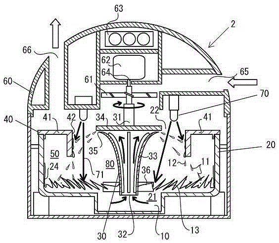
[0093] Example 2, see image 3 The chlorine dioxide gas generator in which the stirring body 36 is added as the surface area expanding unit in the first embodiment will be described. image 3 It is a cross-sectional view of the chlorine dioxide gas generator 2 having the stirring body 36 that stirs the water surface outside the front end of the water drop scatterer 30 . In Example 2, the configuration other than the agitator 36 is the same as that of Example 1, so the same reference numerals are assigned to the drawings and descriptions thereof are omitted.

[0094] By rotating the stirring body 36, the stable chlorine dioxide water 10 is vigorously stirred to make the water surface 13 fluctuate up and down, expand the surface area, and simultaneously increase the stable chlorine dioxide water 10 attached to the lower part 24 of the side wall. Therefore compared with Example 1, the surface area of ​​the stabilized chlorine dioxide water 10 irradiated by the ultraviolet ray 71...

Embodiment 3

[0096] Example 3, see Figure 4 The chlorine dioxide gas generating device 3 using the foamed component as the surface area expanding component will be described. Figure 4 This is a cross-sectional view illustrating the chlorine dioxide gas generator 3 provided with the air pump 90 . Next, the surface-area-enlarging member of the foam member constituting the main part of Example 3 will be described. The foaming unit includes an air pump 90 and a pipe 91 . Parts having the same configuration as those in Embodiment 1 are given the same reference numerals in the drawings, and description thereof will be omitted.

[0097] The air pump 90 is arranged on the top cover 60 and connected to the pipe 91 arranged on the storage tank 20 . The end portion of the pipe member 91 is adapted to be disposed on the recessed portion 21 of the storage tank 20 . Here, the air pump 90 only needs to be able to introduce air into the chlorine dioxide generating space 80, and it can also be an exi...


PUM


Abstract

The present invention expands, by using a surface-area expansion means (30), the surface area of a stabilized chlorine dioxide solution (10) which is irradiated with ultraviolet rays (71) and stored in a storage tank (20), quickly generates a chlorine dioxide gas, and discharges the gas to the exterior of the vessel by using a ventilation means (61). The chlorine dioxide gas is stably discharged by irradiating the stabilized chlorine dioxide liquid with ultraviolet rays. It is possible to adjust the concentration of the generated chlorine dioxide gas by adjusting the concentration of the stabilized chlorine dioxide solution (10) and the ultraviolet ray (71) output. By directly discharging a low-concentration chlorine dioxide gas that is safe for people into the interior of a room in which people live, it is possible to sterilize the interior of the room from corner to corner. When the concentration thereof is high, it is possible to sterilize a medical device inside a medical-device sterilization box. As a result, it is possible to provide a chlorine-dioxide-gas generation device which makes it possible to quickly and sustainably generate chlorine-dioxide gas and easily manage the concentration of the chlorine-dioxide gas.

Description

technical field [0001] The present invention relates to a chlorine dioxide gas generating device for generating chlorine dioxide gas in a space to purify the air in the space, and to a sterilization box for medical equipment. Specifically, the present invention relates to a chlorine dioxide gas generating device that expands the surface area of ​​stable chlorine dioxide water stored in a chlorine dioxide gas generating device and irradiates ultraviolet rays to generate chlorine dioxide gas, and a medical device for sterilization box. Background technique [0002] Viruses such as influenza virus, fungi such as mold, other bacteria, miscellaneous bacteria, etc. are easily mixed in the air in the living space where people work or live. In recent years, due to the epidemic of new influenza and allergies caused by mold and other causes, the impact on health has attracted much attention. In order to cope with such a problem, various air cleaners such as home use, business use, a...

Claims


Application Information

Patent Timeline
Patent Type & Authority Patents(China)
IPC IPC(8): B01J7/00A61L2/20A61L9/01A61L9/04A61L9/20C01B11/02
CPCA61L2/20A61L9/122A61L2202/11A61L2202/14A61L2202/24A61L2209/11A61L2209/21B01J7/00A61L2/10A61L2209/16C01B11/023A61B50/00A61L9/015
Inventor 松永敏宏山本秀树石井健三
Owner FM IWATE
Why Eureka
Try Eureka