
Multifunctional pop-up knife structure

A pop-up, multi-functional technology, applied in the direction of lathe tools, grinding tools, cutting blades, etc., can solve the problems of long turnaround time of parts, high cost, low production efficiency of enterprises, etc., achieve high flexural strength, use The effect of simple and compact structure

Active Publication Date: 2017-04-05
LANDING GEAR ADVANCED MFG
View PDF6 Cites 0 Cited by
  • Summary
  • Abstract
  • Description
  • Claims
  • Application Information

AI Technical Summary

Problems solved by technology

However, this traditional method is not only inefficient, but also often limited by the processing length of processing equipment. As far as deep hole tools are concerned, their high cost and harsh equipment requirements are not suitable for single-piece and small-batch production in the scientific research process. Production; if the machining plan with extended tool holder and large-stroke machine tool is adopted, the turnaround time of parts will be long, the replacement of tools will take a lot of time, and the production efficiency of the enterprise will be low
[0003] In aviation products, some piston rod parts with deep hole grooves or inner holes in the rotary body are often encountered, which cannot be completed by general deep hole processing equipment

Method used


Image

  • Multifunctional pop-up knife structure
  • Multifunctional pop-up knife structure
  • Multifunctional pop-up knife structure

Examples


Embodiment Construction

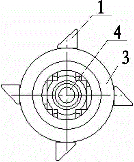
[0021] Such as Figure 1-Figure 4 As shown, the multifunctional pop-up cutter mechanism of the present invention includes a cylindrical cutter housing 3, the middle part and the front end of the cutter housing 3 are provided with U-shaped grooves 7, and the front part of the cutter housing 3 is provided with The four limiting grooves 8 having the same size and communicating with the inner cavity of the cutter housing 3 make the radial section of the inner cavity of the front end of the cutter housing 3 present a cross shape. A movable knife holder 1 is embedded in each limiting groove 8 .

[0022] The movable tool holder 1 includes a tool holder base 11 on which a cutting tool 12 is arranged, and two splints 13 are fastened on the tool holder base 11 by screws to clamp the cutting tool 12 at the same time. The rear end of the knife rest base 11 and the front end of the splint 13 offer a positioning groove 14 that matches the U-shaped groove 7 on the cutter body shell 3 and is...


PUM


Abstract

The invention discloses a multifunctional pop-up tool structure, which comprises a tubular tool body shell; a plurality of limiting grooves communicated with the inner cavity of the tool body shell are formed in the front part of the tool body shell; a movable tool head is embedded into each limiting groove; the movable tool heads and the tool body shell are fixedly installed through a first elastic fixation piston ring and a second elastic fixation piston ring; a cutting tool is arranged at the upper part of each movable tool head; the bottom part of each movable tool head is a tool rest substrate; a plurality of chutes are formed in the bottom part of each tool rest substrate; an adjusting mandrel is arranged in the inner cavity of the tool body shell, and moreover, the front end of the adjusting mandrel is connected with a jackstay; the adjusting mandrel is also provided with multiple groups of bosses; the side face of each boss forms a second oblique plane; the second oblique planes are respectively matched with the chutes of the movable tool heads; during a process that the adjusting mandrel is propelled forwards, the second oblique planes of the multiple groups of bosses respectively abut on the chutes of the movable tool heads, so that the front end of each movable tool head is gradually expanded outwards to realize adjustment on the tool processing radius.

Description

technical field [0001] The invention relates to a cutting tool structure, especially one that can be applied to the processing of deep-hole annular grooves of special-shaped parts such as oil grooves, retaining ring grooves and tool relief grooves. It also takes into account the processing of inner holes of ordinary parts, and also has cutting and boring. , grinding and other functions of the multi-functional pop-up cutter. Background technique [0002] When the internal groove of the part is too deep or the rotary structure is relatively complicated, the processing method of using traditional deep hole cutters or lengthening the tool bar with a large-stroke lathe can solve the processing of most parts. However, this traditional method is not only inefficient, but also often limited by the processing length of processing equipment. As far as deep hole tools are concerned, their high cost and harsh equipment requirements are not suitable for single-piece and small-batch produ...

Claims


Application Information

Patent Timeline
Patent Type & Authority Patents(China)
IPC IPC(8): B23B27/00B24B37/11
CPCB23B27/00B23B2205/12B24B37/11
Inventor 田辉王义宝沈勇郭辉肖斌岳临峰
Owner LANDING GEAR ADVANCED MFG
Learn More