Reinforcement method for single beam bearing of bridge and construction method thereof
A technology of single-board force and construction method, which is applied in bridge reinforcement, bridge, bridge maintenance, etc., can solve the problems of affecting the reinforcement effect and the difficulty of small hinge gaps, etc., and achieve the effect of convenient construction and improvement of lateral force
- Summary
- Abstract
- Description
- Claims
- Application Information
AI Technical Summary
Problems solved by technology
Method used
Image

Examples
Embodiment 1
[0033] Another object of the present invention is to provide a construction method for reinforced bridge veneers, comprising the following steps:
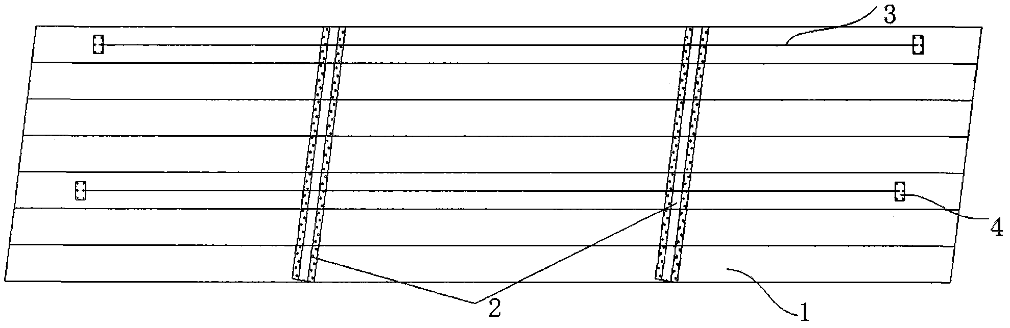
[0034] Step 1, perform horizontal lofting and positioning at the position where the beam needs to be set;
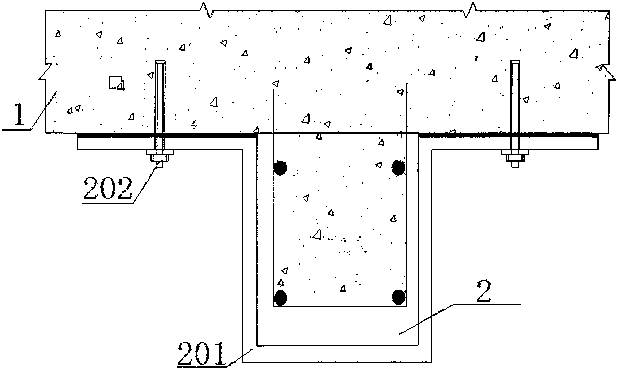
[0035] Step 2, roughen the surface of the positioning position, and punch holes according to the hole positions on the U-shaped steel flange;
[0036] Step 3, clear the hole and embed steel bars and anchor screws in the hole;
[0037] Step 4, Anchor and install U-shaped steel at the positioning position;
[0038] Step 5, pouring concrete into the U-shaped steel.
Embodiment 2
[0040] A construction method for stress-strengthening a bridge veneer, comprising the following steps:
[0041] Step 1, washing and repairing the beam and slab defects;
[0042] Step 2, perform horizontal lofting and positioning at the position where the beam needs to be set;
[0043] Step 3, roughen the surface of the positioning position, and punch holes according to the hole positions on the U-shaped steel flange;
[0044] Step 4, clear the hole and embed steel bars and anchor screws in the hole;
[0045] Step 5, Anchor and install U-shaped steel at the positioning position;
[0046] Step 6, pouring concrete into the U-shaped steel.
Embodiment 3
[0048] A construction method for stress-strengthening a bridge veneer, comprising the following steps:
[0049] Step 1, perform horizontal lofting and positioning at the position where the beam needs to be set;
[0050] Step 2, roughen the surface of the positioning position, and punch holes according to the hole positions on the U-shaped steel flange;
[0051] Step 3, clear the hole and embed steel bars and anchor screws in the hole;
[0052] Step 4, Anchor and install U-shaped steel at the positioning position;
[0053] Step 5, pouring concrete into the U-shaped steel.
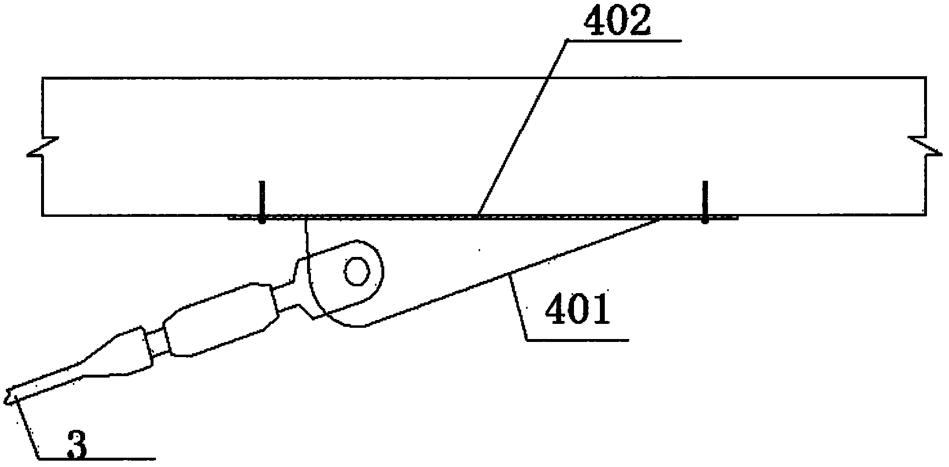
[0054] Step 6, install anchor ends of stay cables at both ends of the vertical beam of the bridge, the anchor ends of stay cables are connected with longitudinal prestressed steel bars, and stretch the prestressed steel bars.
PUM
 Abstract
Description
Claims
Application Information
 - R&D
- Intellectual Property
- Life Sciences
- Materials
- Tech Scout
- Unparalleled Data Quality
- Higher Quality Content
- 60% Fewer Hallucinations
Browse by: Latest US Patents, China's latest patents, Technical Efficacy Thesaurus, Application Domain, Technology Topic, Popular Technical Reports.
© 2025 PatSnap. All rights reserved.Legal|Privacy policy|Modern Slavery Act Transparency Statement|Sitemap|About US| Contact US: help@patsnap.com