Transmission mechanism for magnetic refrigerator

A technology of transmission mechanism and magnetic refrigerator, which is applied in transmission devices, mechanical energy control, electromechanical devices, etc., can solve the problems of high manufacturing and processing costs, low work efficiency, and high installation accuracy, and achieve low manufacturing costs, good cooling effect, The effect of motion trajectory stabilization

Inactive Publication Date: 2015-02-04
SOUTH CHINA UNIV OF TECH
View PDF8 Cites 13 Cited by
  • Summary
  • Abstract
  • Description
  • Claims
  • Application Information

AI Technical Summary

Problems solved by technology

[0009] To sum up, the structure of the existing linear transmission device has its advantages and disadvantages according to the use requirements. In practical applications, in some special occasions, such as magnetic refrigeration and other transmission devices that require entering a narrow space for work, the existing technology cannot meet this requirement. Require
At the same time, the current linear transmission device either has a complex structure, high manufacturing and processing costs, high installation accuracy, or low work efficiency.

Method used


Image

  • Transmission mechanism for magnetic refrigerator
  • Transmission mechanism for magnetic refrigerator
  • Transmission mechanism for magnetic refrigerator

Examples


Embodiment Construction

[0032] The purpose of the invention of the present invention will be described in further detail below in conjunction with the accompanying drawings and specific embodiments, and the embodiments cannot be repeated here one by one, but the implementation of the present invention is not therefore limited to the following embodiments.

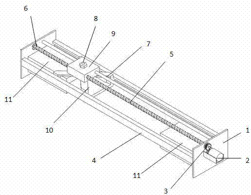
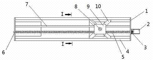
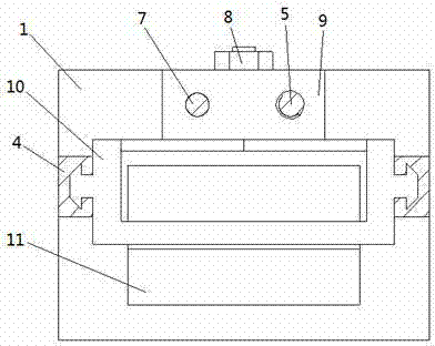
[0033] like Figures 1 to 3 As shown, a transmission mechanism for a magnetic refrigerator includes a screw rod 5 and a slider 9 threadedly engaged with the screw rod 5, the screw rod 5 is rotatably connected and arranged between the bases 1 through a bearing 6, and It includes a claw-shaped packaging box 10, a linear sliding guide rail 4 arranged in parallel between the bases 1, the top of the claw-shaped packaging box 10 is fixedly connected with a slider 9 through a bolt 8, and the two sides of the claw-shaped packaging box 10 Slidingly matched with the linear sliding guide rail 4, a motor 2 is provided on the outside of the base 1 to drive the...


PUM


Abstract

The invention discloses a transmission mechanism for a magnetic refrigerator. The transmission mechanism comprises a lead screw and a sliding block in screw thread fit with the lead screw, wherein the lead screw is connected and arranged between bases in a rotating mode through a bearing. The transmission mechanism further comprises a claw type packaging box and linear slide rails, wherein the linear slide rails are connected and arranged between the bases in parallel; the top end of the claw type packaging box is fixedly connected with the sliding block through a bolt; the two sides of the claw type packaging box are in sliding fit with the linear slide rails; motors driving the lead screw to rotate through a gear pair are arranged on the outer sides of the bases; U-shaped magnets are respectively arranged on the inner sides of the two ends of the bases. The transmission mechanism is simple and compact in structure and relatively low in cost; the transmission mechanism is stable in transmission and high in transmission efficiency, and linear reciprocating motion of the claw type packaging box can be realized; the claw type packaging box is of a claw type structure, so that the sliding block in the lead screw device can be mounted on the top of the claw type packaging box, so that the space is saved, and the claw type packaging box can be driven to enter a narrow space without being obstructed by the magnets; therefore, the transmission mechanism can be applied to working environments with narrow spaces.

Description

technical field [0001] The invention belongs to the technical field of machinery, in particular to a transmission mechanism for a magnetic refrigerator, which can realize the transmission device that converts the rotational motion of a motor into the reciprocating linear motion of a packaging box. Background technique [0002] As a high-tech green refrigeration technology, magnetic refrigeration has the following advantages compared with the traditional compression refrigeration cycle: (1) Environmental protection and pollution-free: the use of Freon and other refrigerants in the traditional compression refrigeration cycle has brought about the environmental problem of ozone layer destruction, Moreover, refrigerants such as ammonia, hydrocarbons, and freon have disadvantages such as poisonous, flammable, easy to leak, and explosive, and the magnetic refrigeration cycle is well overcome due to the use of magnetic refrigerants of solid materials and water as the heat exchange f...

Claims


Application Information

Patent Timeline
Patent Type & Authority Applications(China)
IPC IPC(8): F16H25/24F16C29/02H02K7/10
CPCF16C29/02F16H25/2418
Inventor 吴兆乾李丽珍王惜慧
Owner SOUTH CHINA UNIV OF TECH
Why Eureka
Try Eureka