
Boiler inside pipe system anti-abrasion cover structure
A technology of internal pipes and anti-wear covers, which is applied to boiler water pipes, lighting and heating equipment, fluid heaters, etc., can solve the problems of increasing safety hazards and slag inclusions in piping systems, reduce hidden dangers, reduce undercuts, and prolong operation the effect of time
- Summary
- Abstract
- Description
- Claims
- Application Information
AI Technical Summary
Problems solved by technology
Method used
Image

Examples
Embodiment Construction
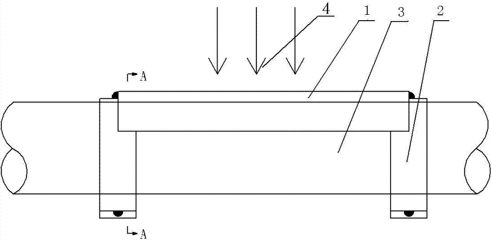
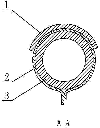
[0012] See figure 1 , figure 2 As shown, a wear-resistant cover structure for the internal piping system of a boiler, which includes a pipe 3 and a wear-resistant cover 1, a pipe clamp 2 that is clamped on the outside of the pipe 3, and the wear-resistant cover 1 is fixed by spot welding on the pipe clamp 2; the pipe clamp 2 It is a circular pipe clamp. The pipe clamp 2 includes the inner surface of the arc. The inner surface of the arc of the pipe clamp 2 matches the outer diameter of the pipe 3. The pipe clamp 2 is clamped on the outside of the pipe 3 so that the pipe clamp 2 is clamped on the Tube 3 on.
[0013] The two ends of the pipe clamp 2 are fixedly connected, which can better realize the clamping of the pipe clamp 2 on the pipe 3; the two ends of the pipe clamp 2 are fixed by spot welding, and can also be fixed by other methods, such as screws and nuts for fixing; the pipe clamp 2 The fixed joints at both ends are arranged along the flue gas flow direction 4, whi...
PUM
 Abstract
Description
Claims
Application Information