Displacement heat exchanger

A volumetric heat exchanger technology, applied in the direction of heat exchanger type, indirect heat exchanger, heat transfer modification, etc., can solve the problem of not achieving effective agitation of water in the upper part of the tank, achieve good descaling effect, improve Heat exchange efficiency, effect of improving efficiency

Inactive Publication Date: 2015-02-04
山东林安热能科技有限公司
View PDF7 Cites 1 Cited by
  • Summary
  • Abstract
  • Description
  • Claims
  • Application Information

AI Technical Summary

Problems solved by technology

However, this utility model does not achieve the effective agitation of the water in the upper part of the tank body, and after the water flow moves in the same direction for a long time, dirt will still form along the moving direction

Method used


Image

  • Displacement heat exchanger
  • Displacement heat exchanger
  • Displacement heat exchanger

Examples


Embodiment Construction

[0018] The features and principles of the present invention will be described in detail below in conjunction with the accompanying drawings, and the examples given are only used to explain the present invention, not to limit the protection scope of the present invention.

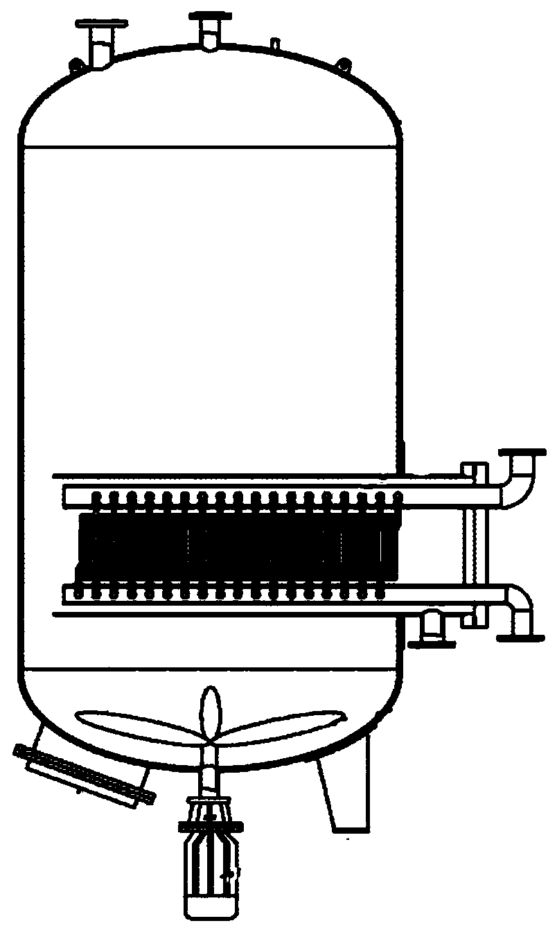
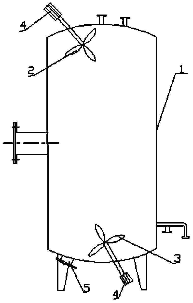
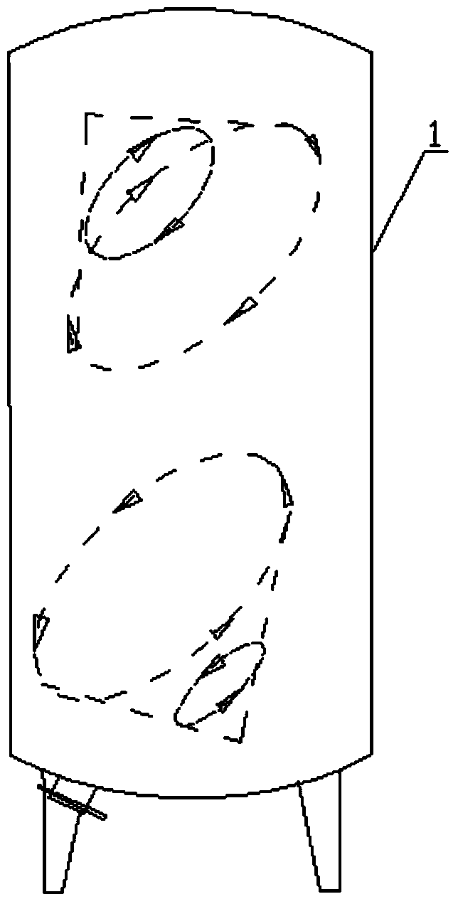
[0019] Such as figure 1 Shown is the structural representation of prior art, figure 2 It is a structural schematic diagram of the present invention, including a tank body 1 and an agitating impeller, the agitating impeller is divided into a first agitating impeller 2 and a second agitating impeller 3, and the first agitating impeller and the second agitating impeller are placed in the tank , and the first agitating impeller and the second agitating impeller are asymmetrically distributed in the tank body 1 and are respectively driven by the motor 4 outside the tank body.

[0020] In order to obtain a better effect, the first agitating impeller and the second agitating impeller are respectively installed on...


PUM


Abstract

The invention relates to a displacement heat exchanger for solving the problem that a heating pipe in the heat exchanger can be scaled easily. The displacement heat exchanger comprises a tank body and stirring impellors. The displacement heat exchanger is characterized in that the stirring impellors comprise a first stirring impellor and a second stirring impellor which are arranged in the tank body and are not distributed symmetrically in the tank body, and are respectively driven by a motor outside the tank body. The displacement heat exchanger enables the outer wall surface of the heating pipe not to be scaled easily, the service life of the heat exchanger is prolonged, and the heat exchanger efficiency is improved.

Description

technical field [0001] The invention relates to the technical field of heat exchangers, in particular to a volumetric heat exchanger. Background technique [0002] The volumetric heat exchangers currently used will generate certain dirt on the internal heating tube bundles. Generally, regular inspections are required for thermal shock once a month, and clean water should be released once a week. The specific method of thermal shock descaling is: drain the water in the tank, keep the steam pressure at 0.3MPa, until the heating pipe makes a sound, indicating that the heating pipe has expanded, then, use the water pipe to impact the heating pipe bundle from the shock pipe for 3-4 consecutive times and wait The scale flakes flow out from the sewage outlet, and then fill up with cold water and start working again. The process is complicated and time-consuming, which affects the heat exchange efficiency of the heat exchanger; in addition, as the method continues to be carried out...

Claims


Application Information

Patent Timeline
Patent Type & Authority Applications(China)
IPC IPC(8): F28D7/00F28F13/12
Inventor 房玉林李营石镇镇
Owner 山东林安热能科技有限公司
Why Eureka
Try Eureka