

Device and method for removing adhering dust of raw materials for iron and steel making
A technology for attaching powder and raw materials, which is applied to chemical instruments and methods, solid separation, filtration, etc., can solve the problems of reduced average particle size of lump ore, increased ventilation resistance, and reduced productivity.
- Summary
- Abstract
- Description
- Claims
- Application Information
AI Technical Summary
Problems solved by technology
Method used
Image

Examples
Embodiment approach 1
[0063] Embodiment 1 of the present invention will be described based on the drawings.
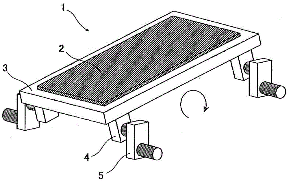
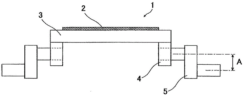
[0064] Use of the iron-making raw material adhering powder removal device of Embodiment 1 figure 1 represents a stereogram, figure 2 The middle shows the swinging rebound type separator (swing screen) 1 of the front view.
[0065] The swing bounce type sorter is a form sorting device that uses the difference in the ballistic trajectory that bounces back on the screen due to the difference in the shape and hardness of the input. The swinging rebound type separator 1 has a mesh screen inclined at a certain angle and an eccentric drive mechanism. The screen has an inclined screen 2 and a screen stand 3 . The eccentric drive mechanism has a crankshaft 5 that is eccentric by an amount A via a bearing 4 . Use the eccentric drive mechanism to make the mesh screen rotate in the opposite direction of inclination ( figure 1 (indicated by the middle arrow), and vibrates in the up and down direct...
Embodiment 1
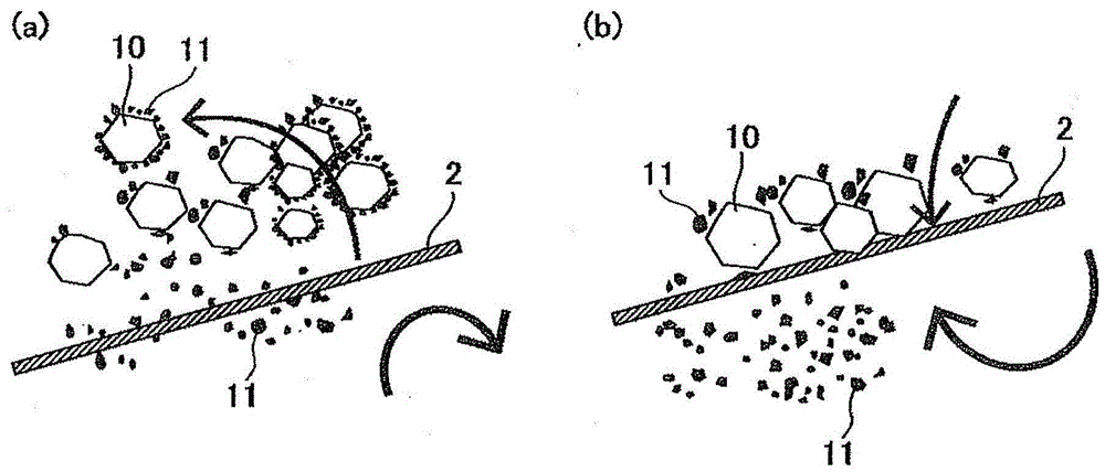
[0074] As an embodiment of the present invention, such as Figure 4 As shown, lump ore 10A of type A of 10 to 50 mm in size with about 10% by mass of fine iron ore 11 of 5 mm or less adhered to the surface is conveyed by belt conveyor 20, and it is thrown into a mine having a sieve opening of 10 mm. The oscillating screen 1 of the inclined screen (rubber screen) 2 collects the lump ore 10B at the end of the inclined lower side of the inclined screen 2, and collects the attached powder 11 directly under the inclined screen 2. At this time, the half amplitude of the inclined screen 2 was set to three modes of 30 mm, 45 mm, and 60 mm, and the rotation speed was set to 120 to 250 rpm.
[0075] Moreover, the lump ore (excluding the lump ore before processing) 10A and the recovered lump ore (excluding the lump ore after processing) 10B before being thrown into the vibrating screen 1 are respectively measured after drying through a sieve with a sieve opening of 5 mm. The amount of f...
Embodiment 2
[0080] Example 2 of the present invention is shown. The method for removing the attached powder is the same as in Example 1, but the lump ore uses another type B (the first embodiment is type A). As the lump ore type B to be supplied, a type in which fine particles of 5 mm or less adhered to about 10% was used.
[0081] The half amplitude of the mesh screen was set to three modes of 30, 45, and 60 mm, and the rotation speed was set to 120 to 250 rpm.
[0082] Figure 7 , 8 The remaining ratio of the attached powder in the examples is shown.
[0083] From Figure 7 It can be seen that, similarly to Example 1, there is a rotational speed region in which the proportion of remaining powder adhered to the smallest value exists in each half-amplitude. in addition, Figure 8 The minimum adhering powder residual ratio is plotted for each half-amplitude. according to Figure 8 , as in Example 1, it can be said that if the half-amplitude is set in the region of 40 to 50 mm, the ...
PUM
 Abstract
Description
Claims
Application Information