Check patentability & draft patents in minutes with Patsnap Eureka AI!

Automatic variable-pitch mechanism for center distance of double-shaft tightening machine

A technology of variable distance mechanism and tightening machine, which is applied in metal processing, metal processing equipment, manufacturing tools, etc. It can solve the problem that the center of the distribution circle cannot coincide with the center of the bolt distribution circle, the adjustment of the position of the tightening shaft is cumbersome and inaccurate, and the center of the tightening shaft The position is not accurate enough to achieve the effect of high production efficiency and automation, simple structure and good self-locking performance

Active Publication Date: 2015-02-11
ANHUI JEE AUTOMATION EQUIP CO LTD
View PDF6 Cites 10 Cited by
  • Summary
  • Abstract
  • Description
  • Claims
  • Application Information

AI Technical Summary

Problems solved by technology

However, in the prior art, the adjustment of the position of the tightening shaft is cumbersome and inaccurate
The specific method used is that the operator uses a caliper to measure the center distance of the tightening shaft while adjusting the position of the tightening shaft. The center of the circle cannot exactly coincide with the center of the bolt distribution circle
Thus affecting the tightening quality, and even making the tightening machine unable to work normally

Method used


Image

  • Automatic variable-pitch mechanism for center distance of double-shaft tightening machine
  • Automatic variable-pitch mechanism for center distance of double-shaft tightening machine
  • Automatic variable-pitch mechanism for center distance of double-shaft tightening machine

Examples


Embodiment Construction

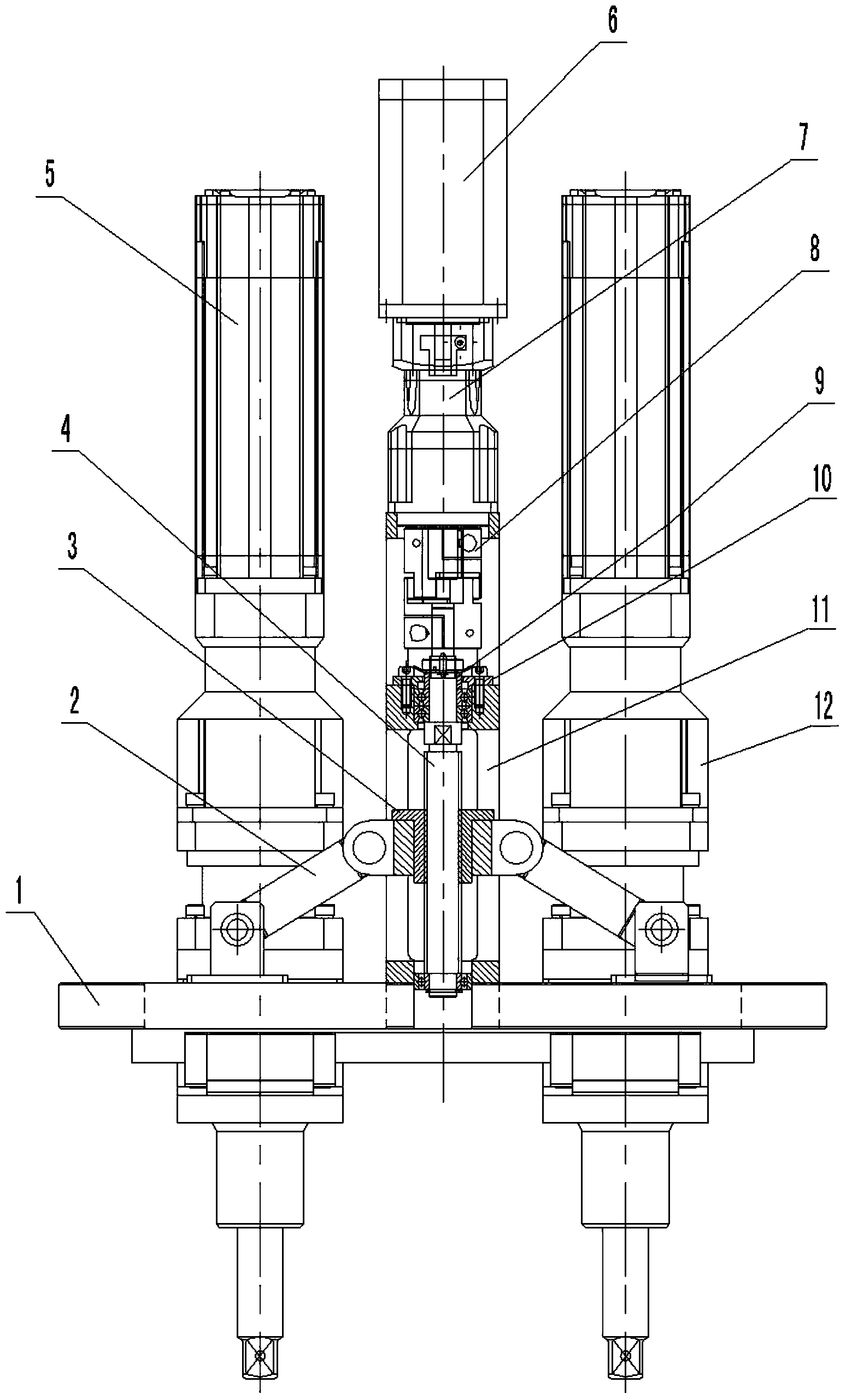
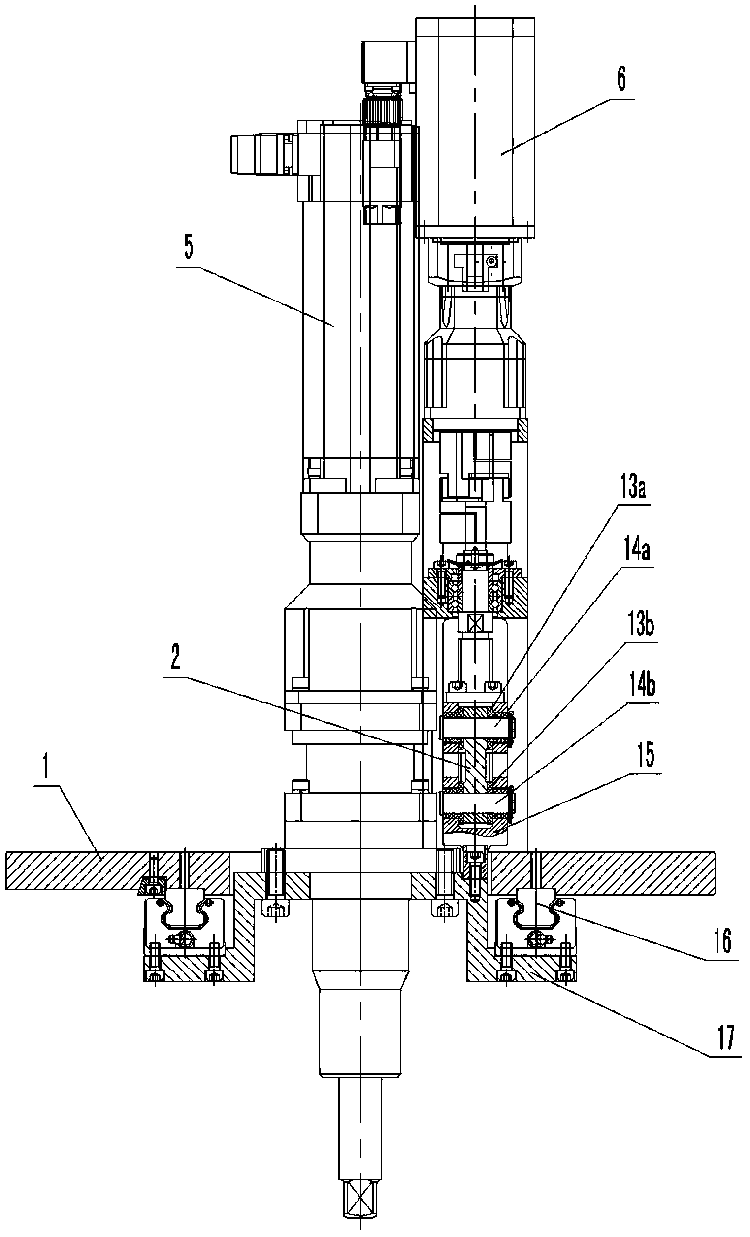
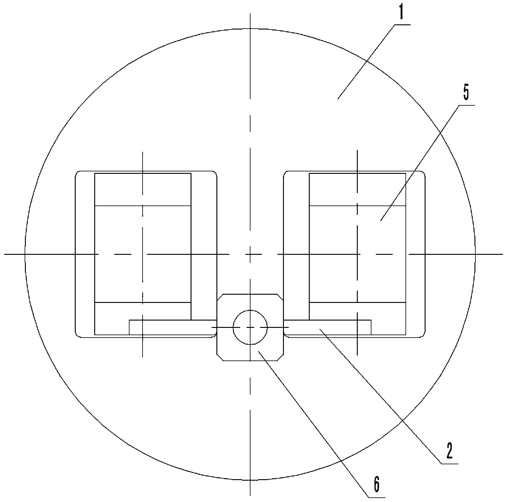
[0020] see figure 1 , figure 2 and image 3 , the structure of the center distance automatic variable distance mechanism of the biaxial tightening machine in this embodiment is set as:

[0021] Two sets of vertical tightening shafts 5 are arranged on the variable-pitch mounting plate 1 fixed horizontally. The diameters of the two sets of tightening shafts 5 are on the same straight line A. The shaft bracket 17 is installed on the pitch-variable mounting plate 1, and the two sets of tightening shafts 5 can move toward each other along the straight line A on the pitch-variable mounting plate 1 driven by the respective tightening shaft brackets 17;

[0022] The screw nut pair is set, the screw mandrel 4 in the screw mandrel nut pair is vertically arranged, the orthographic projection of the screw mandrel 4 and the two sets of tightening shafts 5 on the pitch-variable mounting plate 1 is in the position of an isosceles triangle, and The orthographic projection of the screw 4 i...


PUM


Abstract

The invention discloses an automatic variable-pitch mechanism for the center distance of a double-shaft tightening machine. The automatic variable-pitch mechanism is characterized in that two sets of vertical tightening shafts are arranged on a variable-pitch mounting plate which is horizontally and fixedly arranged; the diameters of the two sets of tightening shafts are positioned on the same straight line A; the two sets of tightening shafts are respectively mounted on the variable-pitch mounting plate through respective tightening shaft supports, and can move in opposite directions along the straight line A under the driving of the respective tightening shaft supports; a lead screw nut pair is arranged, a lead screw in the lead screw nut pair is vertically arranged, the orthographic projections of the lead screw and the two sets of tightening shafts on the variable-pitch mounting plate are positioned at the position of an isosceles triangle, and the orthographic projection of the lead screw is positioned at the position of the vertex of a triangle; nuts in the lead screw nut pair on the two sides are respectively connected with the tightening shaft support on the corresponding side through connecting rods; the connecting rods are respectively hinged to the nuts and the tightening shaft support. The two sets of tightening shafts are driven to move in opposite directions along the straight line A through the lead screw nut pair by using a servo motor to obtain the required center distance, and the mechanism is suitable for bolt tightening of various products.

Description

technical field [0001] The present invention relates to the center distance automatic variable distance mechanism of the main reducer differential housing bolts and toothed bolts double-axis tightening machine, more specifically to complete the transformation of the center distance between the two tightening shafts in the assembly process of the differential gear assembly. Thereby, it is an automatic pitch-variable mechanism for tightening bolts with different center distances. Background technique [0002] In the automobile assembly production line, a large number of bolts need to be tightened during the assembly process of the differential housing assembly of the drive axle main reducer, and a double-axis tightening machine is used for the tightening operation. In terms of adapting to the range of products, there are two types of double-axis tightening machines. One is specially designed for a certain product, and the center distance of the tightening shaft cannot be adjus...

Claims


Application Information

Patent Timeline
Patent Type & Authority Applications(China)
IPC IPC(8): B23P19/06
CPCB23P19/069
Inventor 刘蕾汪波宋增广彭教慧
Owner ANHUI JEE AUTOMATION EQUIP CO LTD
Features
  • R&D
  • Intellectual Property
  • Life Sciences
  • Materials
  • Tech Scout
  • Unparalleled Data Quality
  • Higher Quality Content
  • 60% Fewer Hallucinations
Learn More