Micro geometrical morphology measurement system

A geometry and measurement technology, applied in the field of differential microscopic geometry measurement systems

Inactive Publication Date: 2015-02-11
FORCE PRECISION INSTR
View PDF7 Cites 4 Cited by
  • Summary
  • Abstract
  • Description
  • Claims
  • Application Information

AI Technical Summary

Problems solved by technology

[0010] Apparently, the current micro-geometry measurement system has not yet been pr

Method used


Image

  • Micro geometrical morphology measurement system
  • Micro geometrical morphology measurement system
  • Micro geometrical morphology measurement system

Examples


Embodiment Construction

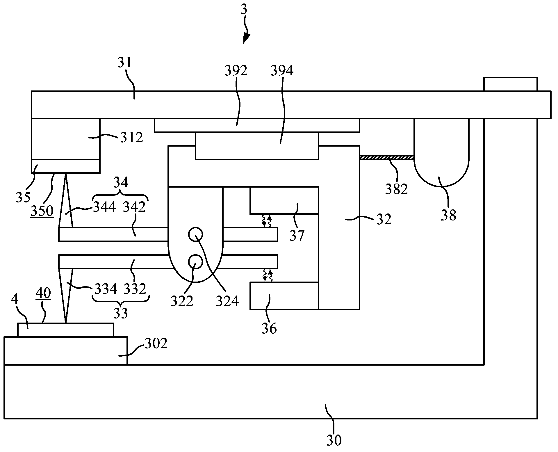
[0082] see figure 2 , the architecture of the micro-geometric topography measurement system 3 of the first preferred embodiment of the present invention is schematically shown in figure 2 middle. The microscopic geometry measurement system 3 of the present invention is used to measure the microscopic geometry of the test piece 4 .

[0083] The microscopic geometry measurement system 3 of the first preferred embodiment of the present invention includes a first scanning device 33, a second scanning device 34, a flat substrate 35, a first displacement sensing device 36, and a second displacement sensing device 37 and processing unit (not shown figure 2 middle). Likewise, the condition of the flat substrate 35 is that its surface roughness must be below sub-millimeters.

[0084] The first scanning device 33 includes a first pivotable arm 332 and a first probe 334 . The first probe 334 is connected to the first pivotable arm 332 and contacts the measuring surface 40 of the ...


PUM


Abstract

The invention provides a micro geometrical morphology measurement system which is used for measuring the micro geometrical morphology of a test piece. The micro geometrical morphology measurement system comprises a first scanning device, a second scanning device and a flat substrate. The first probe of the first scanning device is contacted with the test piece. The second probe of the second scanning device is contacted with the flat substrate. The second scanning device or the flat substrate and the first scanning device are synchronously actuated so that the first probe is enabled to move on the test piece and the second probe is enabled to move on the flat substrate. The micro geometrical morphology of the test piece is obtained via calculation of first displacement of the first pivotally rotatable arm of the first scanning device and second displacement of the second pivotally rotatable arm of the second scanning device.

Description

technical field [0001] The present invention relates to a microscopic geometry system, and in particular, to a differential microscopic geometry system using two probes. Background technique [0002] see figure 1 , the architecture of the prior art micro-geometric topography measurement system 1 is schematically shown in figure 1 middle. The microscopic geometry measurement system 1 is used for measuring the microscopic geometry of the test piece 2 . [0003] The microscopic geometry measurement system 1 includes a base 10 , a lifting platform 11 , a scanning and traversing platform 12 , a scanning device 13 , a flat substrate 15 , a displacement sensing device 16 and an actuating device 18 . [0004] The flat substrate 15 is fixed on the base 10 . The test piece 2 is placed on the scanning traverse table 12 . The scanning traverse stage 12 is arranged on the scanning traverse stage 12 . The scanning traverse stage 12 is structured such that it can move on a flat subst...

Claims


Application Information

Patent Timeline
IPC IPC(8): G01B11/24G01B7/28
Inventor 李嘉宜洪绍刚
Owner FORCE PRECISION INSTR
Why Eureka
Try Eureka