
Three-wire-system thermal resistor measuring circuit

A technology for measuring circuits and thermal resistances, applied in measuring devices, measuring heat, thermometers using electrical/magnetic components directly sensitive to heat, etc. Improve temperature measurement accuracy, avoid measurement errors, and achieve the effect of simple methods

Active Publication Date: 2015-02-11
SHANGHAI MICRO ELECTRONICS EQUIP (GRP) CO LTD
View PDF7 Cites 9 Cited by
  • Summary
  • Abstract
  • Description
  • Claims
  • Application Information

AI Technical Summary

Problems solved by technology

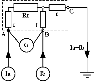
Although this method can eliminate the influence of the wire resistance r on the measurement results, its measurement accuracy is based on the good consistency of the currents of the two constant current sources.
In practical applications, any constant current source will have time drift and temperature drift, and the consistency of the constant current source will be affected, resulting in large measurement errors
[0005] Chinese patent 200810036435.6 discloses a thermal resistance three-wire system, four-wire system multiplexing temperature measurement method, the invention disclosed three-wire thermal resistance measurement method is not accurate, and does not take into account the matching accuracy of the double constant current source
[0006] Chinese patent 201110161316.5 discloses a method for reducing the measurement error of the three-wire thermal resistance. Although the measurement method of the three-wire thermal resistance disclosed in the invention can greatly reduce the influence of the matching error of the double constant current source on the sampling value of the thermal resistance, it needs to increase The additional control circuit realizes the switching of the connection relationship between the two constant current sources and the thermal resistance, which increases the complexity of the measurement system and is not conducive to the remote measurement of temperature

Method used


Image

  • Three-wire-system thermal resistor measuring circuit
  • Three-wire-system thermal resistor measuring circuit
  • Three-wire-system thermal resistor measuring circuit

Examples


Embodiment Construction

[0022] Specific embodiments of the present invention will be described in detail below in conjunction with the accompanying drawings.

[0023] Existing technology uses dual constant current source excitation for the measurement of thermal resistance, and there is a measurement error caused by the inconsistency of the dual constant current source; the prior art uses a multiplex switch (MUX) to switch the connection between the dual constant current source and the thermal resistance The method of measuring the thermal resistance twice before and after and calculating the average value can solve the problem of measurement error caused by the inconsistency of the double constant current source, and additionally increase the complexity of the control circuit, which is not conducive to the remote measurement of temperature.

[0024] In order to overcome the defects in the prior art, the present invention provides a three-wire thermal resistance measurement circuit with a single const...


PUM


Abstract

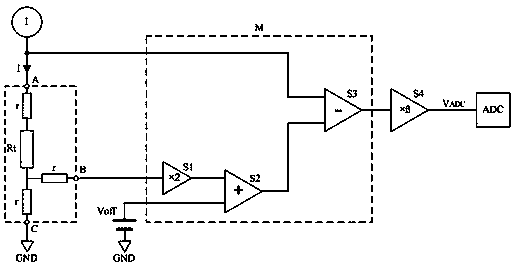
The invention discloses a three-wire-system thermal resistor measuring circuit. The three-wire-system thermal resistor measuring circuit comprises: a constant current source is connected with a first terminal which is connected with a three-wire-system thermal resistor, for providing excitation for the three-wire-system thermal resistor; the first input end of a signal conditioning module is connected with the constant current source, the second input end of the signal conditioning module is connected with a second terminal which is connected with the three-wire-system thermal resistor, and the third input end of the signal conditioning module is connected with DC bias voltage; and the output end of the signal conditioning module is connected with the input end of an amplification circuit, the output end of the amplification circuit is connected with an A / D sampler, and the voltage of the A / D sampler forms a linear relation with the resistance of the thermal resistor.

Description

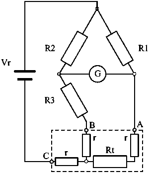
technical field [0001] The invention relates to the technical field of high-precision temperature measurement, in particular to a three-wire thermal resistance measurement circuit. Background technique [0002] High-precision temperature measurement is an important topic in the field of industrial production. The thermal resistance made of metal platinum material has become an ideal temperature measuring element widely used in industrial temperature measuring systems due to its high precision, stability, reproducibility and good interchangeability. Since the three-wire thermal resistance has the characteristics of low cost, convenient wiring, and high measurement accuracy, it is currently the most commonly used thermal resistance wiring method. The widely used three-wire thermal resistance measurement methods include the unbalanced bridge method and the double constant current source method. [0003] Such as figure 1 Shown is the measurement principle diagram of the three...

Claims


Application Information

Patent Timeline
IPC IPC(8): G01K7/18
Inventor 方欣
Owner SHANGHAI MICRO ELECTRONICS EQUIP (GRP) CO LTD
Learn More