Electronic toll collection method and system integrated with path identification function

An electronic non-stop and path recognition technology applied in the field of intelligent transportation to ensure safety and improve efficiency

Inactive Publication Date: 2015-02-11
AEROSPACE INFORMATION
View PDF5 Cites 10 Cited by
  • Summary
  • Abstract
  • Description
  • Claims
  • Application Information

AI Technical Summary

Problems solved by technology

[0005] At present, there is no method to effectively combine the fast and convenient advantages of ETC lanes with multi-path technology in the prior art

Method used


Image

  • Electronic toll collection method and system integrated with path identification function
  • Electronic toll collection method and system integrated with path identification function
  • Electronic toll collection method and system integrated with path identification function

Examples


Embodiment 1

[0036] On the basis of the ETC system, the embodiment of the present invention can seamlessly combine the ETC system and the path identification technology by utilizing the hardware resources of the original ETC system. Expressway traffic and accurate billing.

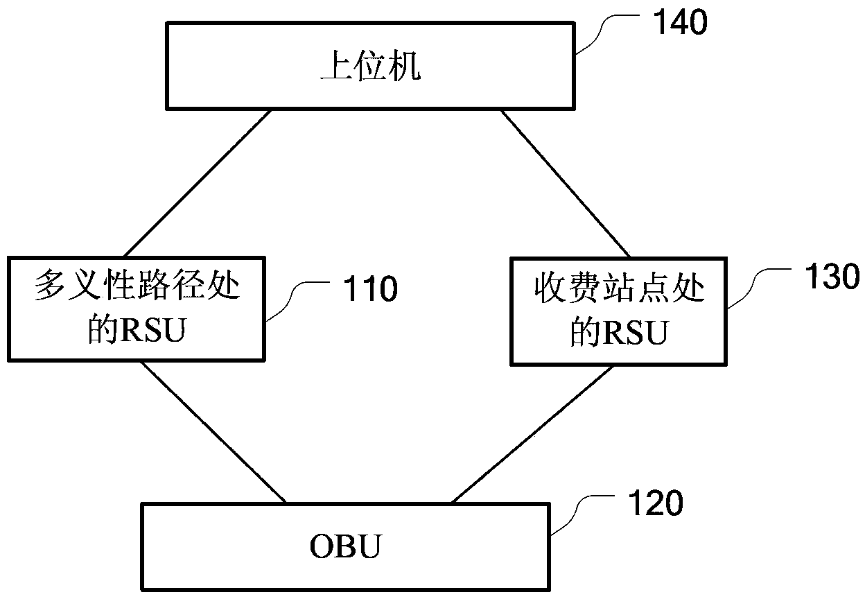
[0037] This embodiment provides an ETC system with integrated path recognition function, and its structural diagram is as follows figure 1 As shown, including: RSU at the ambiguous path, OBU, RSU at the toll station and the host computer.

[0038] The RSU at the ambiguous path is configured to send a radio frequency signal carrying path information corresponding to the RSU to the OBU on the vehicle when the vehicle enters the communication area of ​​the RSU;

[0039] OBU, used to send the radio frequency signal carrying vehicle information to the RSU at the ambiguous path when the vehicle passes through the communication area of ​​the RSU at the ambiguous path, and the path for sending the RSU at the ambiguous path T...

Embodiment 2

[0061] This embodiment provides a schematic diagram of the service processing flow of the RSU at the ambiguous path, as shown in Figure 4 As shown, the following processing steps are included:

[0062] Step S410, the vehicle equipped with the OBU passes through the communication area of ​​the RSU erected at the ambiguous path.

[0063] Step S420, the RSU at the ambiguous path searches for the OBU on the vehicle, and establishes a communication link with the OBU.

[0064] Step S430, the OBU of the vehicle above sends a radio frequency signal in the 5.80 GHz frequency band carrying vehicle information to the RSU at the above ambiguous path.

[0065] The RSU at the above-mentioned ambiguous path judges whether the OBU installed on the vehicle and the vehicle information in the OBU are legal by reading the vehicle information in the radio frequency signal sent by the OBU. If the judging result of the above legality is illegal, execute step S440; otherwise, execute step S450.

...


PUM


Abstract

The embodiment of the invention provides an electronic toll collection method and system integrated with a path identification function. The method mainly comprises the following steps that when a vehicle enters a communication area of an RSU (Roadside Unit) on an ambiguity path, the RSU on the ambiguity path sends radio frequency signals carrying corresponding path information of the RSU to an OBU (On-board Unit) on the vehicle; when the vehicle passes by the RSU at a toll station, the vehicle sends the radio frequency signals carrying the path information and vehicle information stored in the vehicle to the RSU at the roll station; the RSU at the toll station carries out the calculation and deduction of tolls on the vehicle according to the path information and the vehicle information carried by the radio frequency signals sent by the OBU. According to the electronic toll collection method and system provided by the embodiment of the invention, the path identification function can be seamlessly integrated into the ETC (Electronic Toll Collection) system, and the rapid traffic capacity of the ETC system and the precise toll clearing capacity of a path identification system are realized, so that the disadvantage that the toll of the ambiguity path can only be collected by an MTC (Manual Toll Collection) operation can be effectively overcome, and thus the efficiency of transport is improved.

Description

technical field [0001] The invention relates to the technical field of intelligent transportation, in particular to an electronic non-stop toll collection method and system integrating path identification functions. Background technique [0002] ETC (Electronic Toll Collection) system is an automatic electronic toll collection system mainly researched and promoted in the world at present. It is suitable for vehicle toll collection solutions in highways and bridges and tunnels with heavy traffic. OBU (On-Board Unit, on-board equipment) is a standard accessory of the ETC system. It is used to install on the front windshield of the vehicle. When the vehicle passes the ETC lane, the OBU communicates with RSU (Roadside Unit, roadside unit) and other equipment , ETC charges can be completed without parking. Thereby increasing the speed of vehicles and effectively solving the problem of traffic jams. [0003] Multi-path identification technology is an important topic in the field...

Claims


Application Information

Patent Timeline
Patent Type & Authority Applications(China)
IPC IPC(8): G07B15/06
CPCG07B15/063
Inventor 李成成刘洋
Owner AEROSPACE INFORMATION
Why Eureka
Try Eureka