Electric fuse structure

A technology of electric fuses and fuses, applied in circuits, electrical components, electric solid devices, etc., can solve the problems of large length of electric fuses, design limitations of metal interconnection lines, and large area of ​​integrated circuit chips, etc., and achieve reduction small area effect

Active Publication Date: 2015-02-11
SEMICON MFG INT (SHANGHAI) CORP
View PDF5 Cites 2 Cited by
  • Summary
  • Abstract
  • Description
  • Claims
  • Application Information

AI Technical Summary

Problems solved by technology

[0006] In order to make the existing electric fuse structure easier to be blown, the length of the electric fuse 3 is relatively large, causing the electric fuse structure to occupy a large area of ​​the integrated circuit chip, so that the layout design of the metal interconnection lines in the integrated circuit chip is subject to many constraints. limit

Method used


Image

  • Electric fuse structure
  • Electric fuse structure
  • Electric fuse structure

Examples


no. 1 example

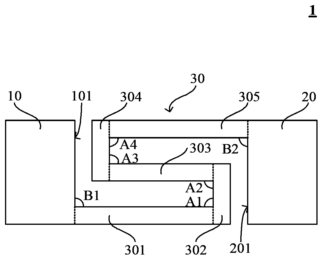
[0036] Such as figure 2 As shown, the electric fuse structure 1 of this embodiment includes: an electric fuse 30, and the electric fuse 30 includes five sub-fuses connected end to end, and the five sub-fuses are respectively: sub-fuses 301, sub-fuses 302, A sub-fuse 303, a sub-fuse 304, and a sub-fuse 305; an anode 10 and a cathode 20 respectively located at both ends of the electric fuse 30 and connected to the electric fuse 30, the anode 10 has a first front 101 facing the cathode 20, The cathode 20 has a second front 201 facing the anode 10, the first front 101 is parallel to the second front 201, and the facing area of ​​the first front 101 and the second front 201 is equal to the area of ​​the first front 101 and the area of ​​the second front 201. area. in:

[0037] The sub-fuse 301 is connected to the first front surface 101 of the anode 10, and the angle B1 between the two is 90 degrees; the sub-fuse 301 is connected to the sub-fuse 302, and the angle A1 between the...

no. 2 example

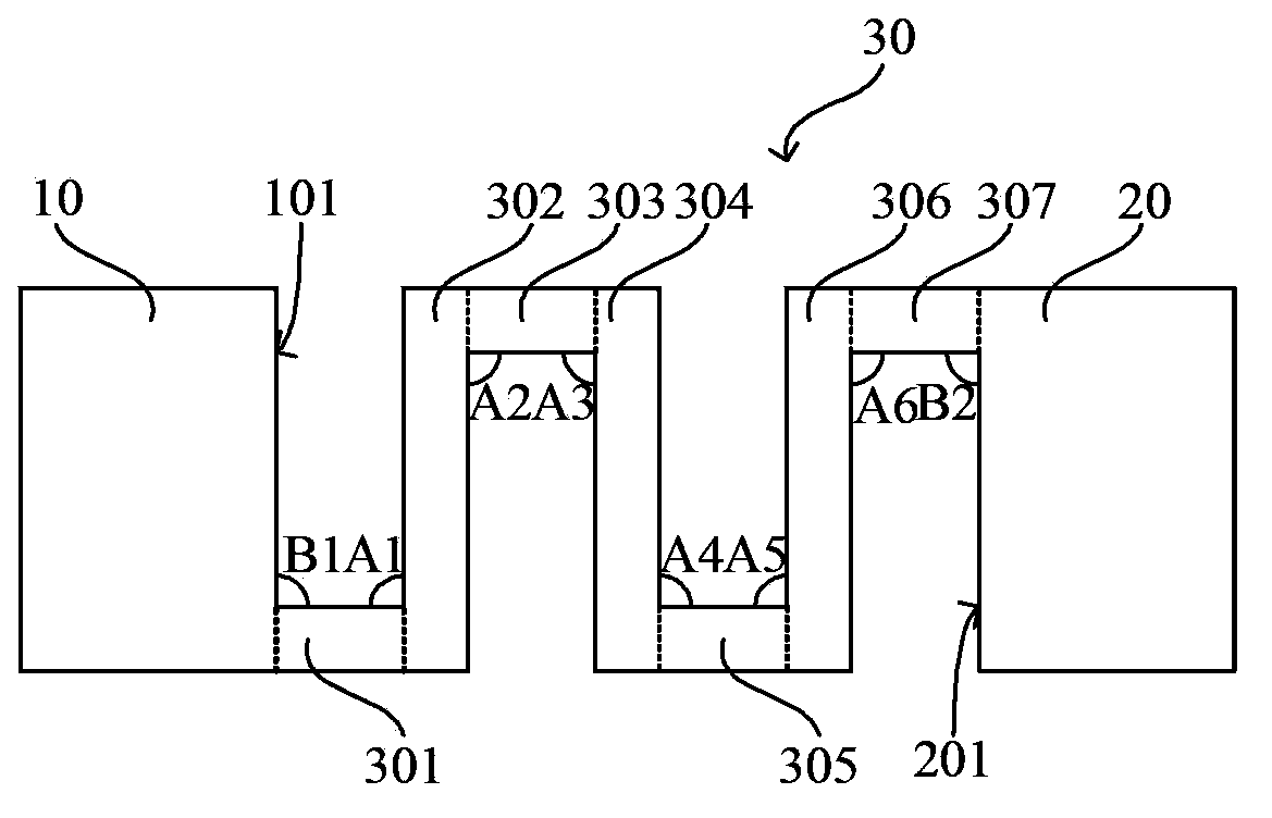
[0043] The difference between the second embodiment and the first embodiment is: as image 3 As shown, the electric fuse 30 includes seven segments of sub-fuse connected end to end. Fuse 306, sub-fuse 307. in:

[0044]The sub-fuse 301 is connected to the first front surface 101 of the anode 10, and the angle B1 between the two is 90 degrees; the sub-fuse 301 is connected to the sub-fuse 302, and the angle A1 between the two is 90 degrees; The sub-fuse 302 is connected to the sub-fuse 303, and the angle A2 between the two is 90 degrees; the sub-fuse 303 is connected to the sub-fuse 304, and the angle A3 between the two is 90 degrees; the sub-fuse 304 It is connected to the sub-fuse 305, and the angle A4 between the two is 90 degrees; the sub-fuse 305 is connected to the sub-fuse 306, and the angle A5 between the two is 90 degrees; the sub-fuse 306 and the sub-fuse 307 The sub-fuse 307 is connected to the second front surface 201 of the cathode 20, and the angle B2 between th...

no. 3 example

[0048] The difference between the third embodiment and the first embodiment is: as Figure 4 As shown, the electric fuse 30 includes seven segments of sub-fuse connected end to end. Fuse 306 , sub-fuse 307 ; in addition, the anode 10 has a first side 102 connected to the first front 101 , and the cathode 20 has a second side 202 connected to the second front 201 . in:

[0049] The sub-fuse 301 is connected to the first side 102 of the anode 10, and the angle B1 between the two is 90 degrees; the sub-fuse 301 is connected to the sub-fuse 302, and the angle A1 between the two is 90 degrees; The sub-fuse 302 is connected to the sub-fuse 303, and the angle A2 between the two is 90 degrees; the sub-fuse 303 is connected to the sub-fuse 304, and the angle A3 between the two is 90 degrees; the sub-fuse 304 It is connected to the sub-fuse 305, and the angle A4 between the two is 90 degrees; the sub-fuse 305 is connected to the sub-fuse 306, and the angle A5 between the two is 90 deg...


PUM


Abstract

The invention discloses an electric fuse structure. The electric fuse structure comprises an electric fuse, and an anode and a cathode which are respectively arranged at two ends of the electric fuse and are connected with the electric fuse, wherein the electric fuse comprises at least three sub electric fuses which are mutually connected end to end, and included angles of every two end-to-end connected sub electric fuses are greater than 0 DEG and smaller than 180 DEG. The electric fuse is guaranteed to have enough large length to make the electric fuse be more easily fused while the distance between the anode and the cathode can be reduced, so the area occupied by the electric fuse structure in an integrated circuit chip can be reduced. When the electric fuse structure and metal interconnection wires are synchronously formed on the integrated circuit chip, layout design of the metal interconnection wires in the integrated circuit chip has more selections.

Description

technical field [0001] The invention relates to the technical field of semiconductors, in particular to an electric fuse structure. Background technique [0002] As feature sizes continue to decrease, semiconductor devices are increasingly susceptible to impurities or defects in the silicon substrate, and the failure of a single diode or MOS transistor often leads to the failure of the entire integrated circuit chip. In order to solve the above problems and improve the yield, some redundant circuits are often formed in the integrated circuit chip. When it is found that some devices cannot work normally after the completion of the manufacturing process, the failed circuit can be electrically isolated from other circuit modules by blowing the fuse structure, and the original failed circuit can be replaced with a redundant circuit. Especially in the manufacturing process of memory, due to the large number of memory cells, it is inevitable that some memory cells will fail, so s...

Claims


Application Information

Patent Timeline
IPC IPC(8): H01L23/525
Inventor 孙光宇
Owner SEMICON MFG INT (SHANGHAI) CORP
Why Eureka
Try Eureka