Fault detection method for circuit sent out from wind power plant
A technology for fault detection and sending out lines, applied in emergency protection circuit devices, electrical components, etc., to solve problems such as inaccurate detection results
- Summary
- Abstract
- Description
- Claims
- Application Information
AI Technical Summary
Problems solved by technology
Method used
Image
Examples
Embodiment
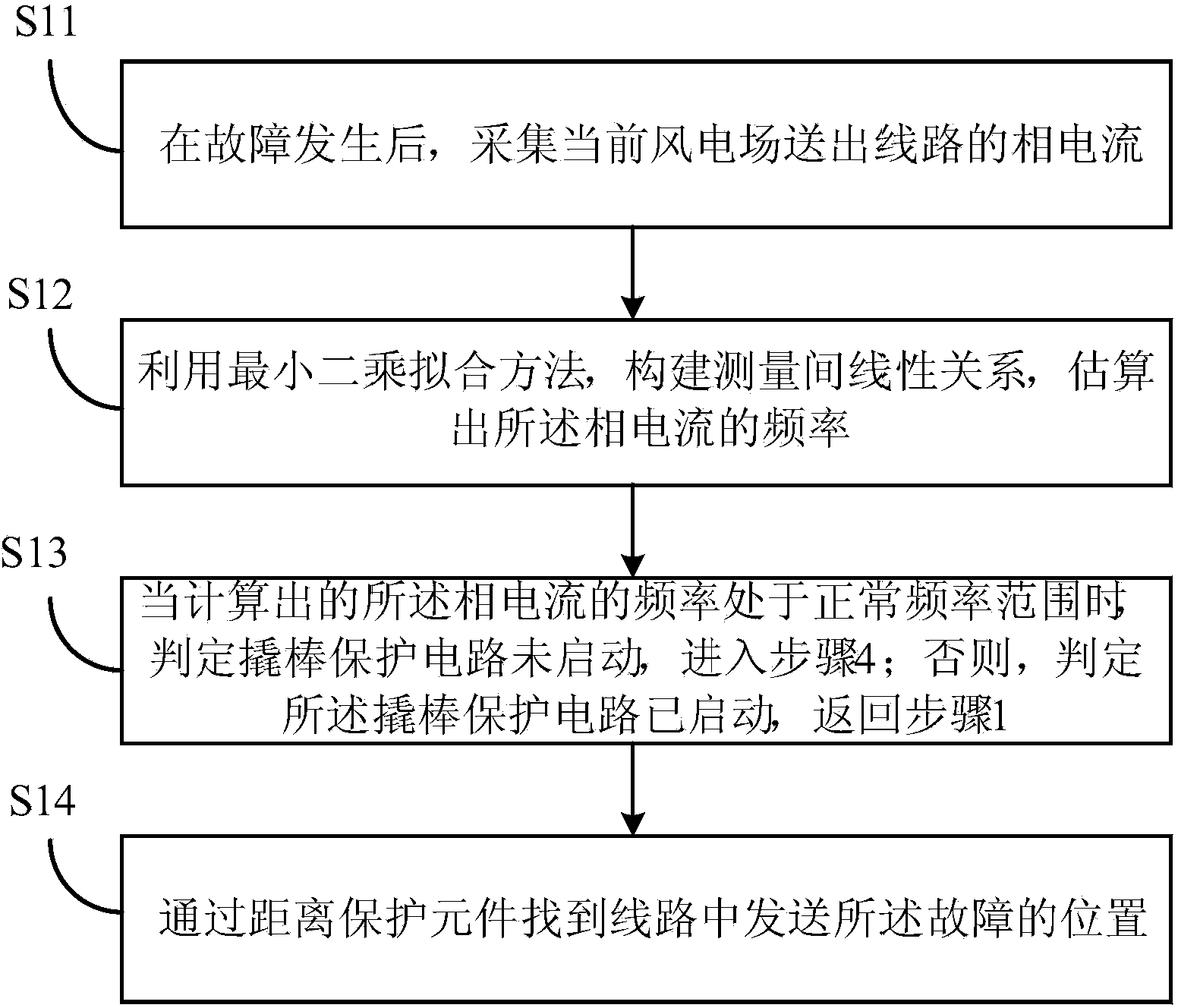
[0026] Step 1: After the fault start module is started, collect the phase current I at the installation place of the line protection sent out from the wind farm through the current transformer A , I B , I C ;
[0027] Step 2: Pass the collected current signal through a low-pass filter to filter out high-order harmonics, and enter step 3 after 0.01s;
[0028] Step 3: Use the least squares fitting method to construct a linear relationship between measurements and estimate the frequency f of the measured signal;
[0029] Step 4: Judging the difference between the frequency f and the system power frequency 50Hz, if they are approximately equal within 0.01s, then go to step 5; Protect the relay and return to step 3;
[0030] Step 5: Use the existing distance protection based on the full-circumference Fourier algorithm to judge the action of the distance protection.
[0031] The details of step 1 are as follows, taking the phase A current as an example:
[0032] After a fault ...
Embodiment 2
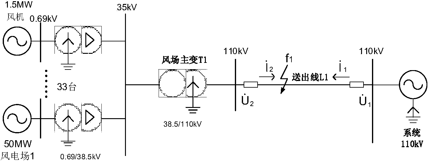
[0056] Such as figure 2 As shown, a doubly-fed wind farm simulation model with 50MW installed capacity is given, the positive sequence impedance of the system is 1.0914+j12.45Ω, and the zero sequence impedance is 5.187+j 22.574Ω. When a three-phase fault occurs on the line at f1, the bus voltage on the wind farm side drops to 20%.
[0057] Methods include:
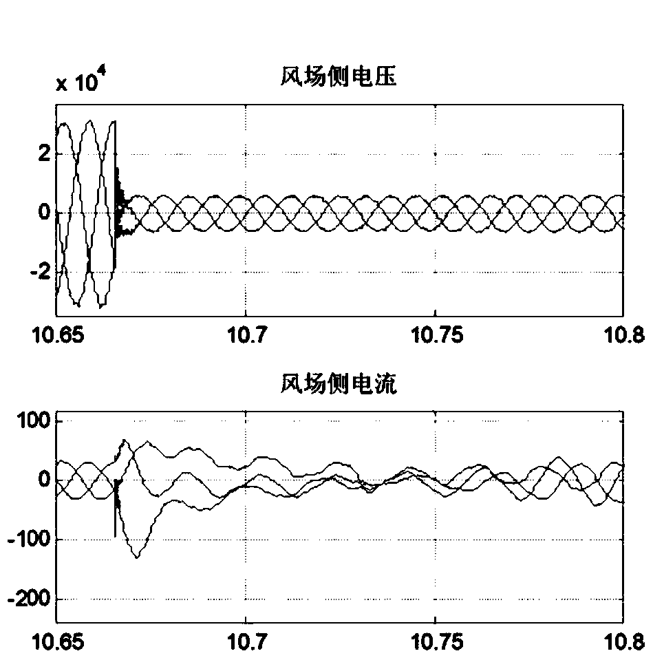
[0058] Step 1: After the fault start module is started, collect the phase current I at the installation place of the line protection sent out from the wind farm through the current transformer A , I B , I C ,Such as image 3 shown;
[0059]Step 2: Pass the collected current signal through a low-pass filter to filter out high-order harmonics, and enter step 3 after 0.01s;
[0060] Step 3: Use the least squares fitting method to construct a linear relationship between measurements and estimate the frequency f of the measured signal. The frequency results calculated at different times are as follows Figure 4 shown; ...
PUM
 Abstract
Description
Claims
Application Information
 - R&D
- Intellectual Property
- Life Sciences
- Materials
- Tech Scout
- Unparalleled Data Quality
- Higher Quality Content
- 60% Fewer Hallucinations
Browse by: Latest US Patents, China's latest patents, Technical Efficacy Thesaurus, Application Domain, Technology Topic, Popular Technical Reports.
© 2025 PatSnap. All rights reserved.Legal|Privacy policy|Modern Slavery Act Transparency Statement|Sitemap|About US| Contact US: help@patsnap.com


