Charging and discharging method of battery pack

A battery pack, charging and discharging technology, applied in battery circuit devices, arrangement of multiple synchronous batteries, collectors, etc., can solve the problems of battery discharge energy waste, heavy burden on the power grid, and large charging and discharging current, and achieve low energy consumption , reduce the types of equipment, and stabilize the voltage

Inactive Publication Date: 2015-02-11
SUZHOU ANKAO ENERGY
View PDF5 Cites 2 Cited by
  • Summary
  • Abstract
  • Description
  • Claims
  • Application Information

AI Technical Summary

Problems solved by technology

The charging and discharging current of the module is very large, and the power supply of the device must also be very large, especially for charging high-voltage battery packs, such as 300V or 500V modules, charging needs to be boosted and consumes more energy.
Moreover, the booster module generally adopts a DC / DC module, which not only has high equipment cost, but also consumes energy itself, which is a heavy burden on the power grid.
[0005] 2. The discharge equipment also consumes external power supply, the discharge energy of the battery is completely wasted, and some of it is recycled, and it becomes an AC boost and feeds back to the grid, which is very troublesome to operate

Method used


Image

  • Charging and discharging method of battery pack
  • Charging and discharging method of battery pack

Examples


Embodiment 1

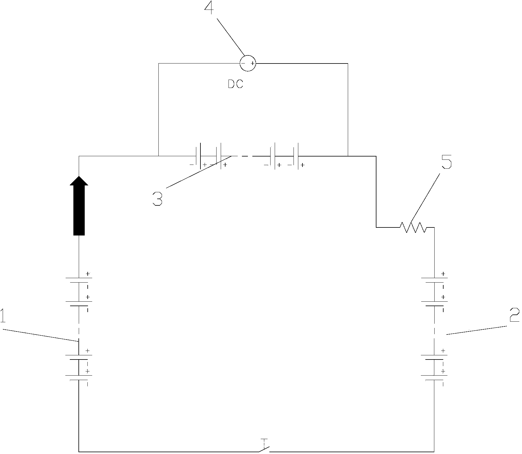
[0024] refer to figure 1 , the charging and discharging method of the battery pack, comprising a discharge battery pack 1 and a rechargeable battery pack 2, there is a voltage difference between the discharge battery pack 1 and the rechargeable battery pack 2, and a step-up energy storage battery is connected in series on the discharge battery pack 1 After group 3, it is connected in parallel with rechargeable battery pack 2 to form a charge-discharge circuit. , the rechargeable battery pack 2 is charged together with the boost energy storage battery pack 3 . The present invention utilizes the pressure difference to realize energy recovery, realizes the charging of the rechargeable battery pack 2 while the discharge battery pack 1 is discharging, makes good use of energy, consumes less energy, and has high efficiency, and boosts the energy storage battery pack 3 through charging The circuit 4 is always maintained in a steady voltage state, which can control the direction of t...

Embodiment 2

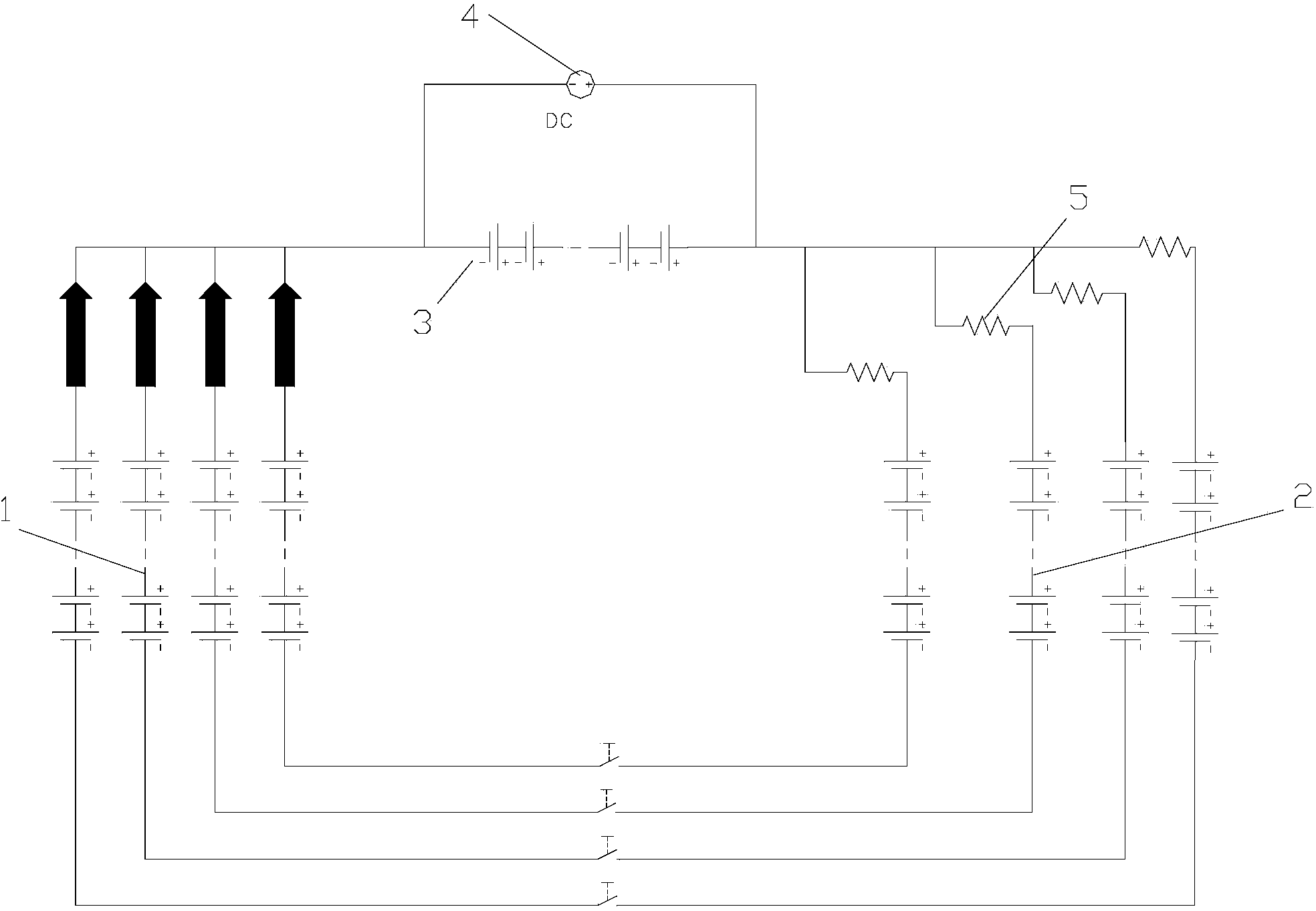
[0031] refer to figure 2 , the difference between this embodiment and Embodiment 1 is that the discharge battery pack 1 is a plurality of discharge battery packs, and the rechargeable battery pack 2 is also a plurality of rechargeable battery packs, each discharge battery pack 1 and one or more After a boosted energy storage battery pack 3 is connected in series, it can form an independent charge-discharge circuit with a corresponding rechargeable battery pack 2 . In this embodiment, multiple charging and discharging circuits can be formed, so that the charging and discharging efficiency is high. The rest of the structures and functions are the same as those in Embodiment 1.


PUM


Abstract

The invention provides a charging and discharging method of a battery pack. According to the charging and discharging method, a discharging battery pack and a charging battery pack are included, wherein a voltage difference is formed between the discharging battery pack and the charging battery pack; the discharging battery pack is connected with a boosting energy-storage battery pack in series and is connected with the charging battery pack in parallel to form a charging-discharging circuit; the boosting energy-storage battery pack is connected with a charging circuit for keeping stable voltage of the boosting energy-storage battery pack; when the discharging battery pack discharges, the discharging battery pack and the boosting energy-storage battery pack are used for charging the charging battery pack. The charging and discharging method of the battery pack has the characteristics of less energy consumption, convenience for operation, high reliability and wide application range.

Description

technical field [0001] The invention relates to a charging and discharging method for a battery pack. Background technique [0002] With the vigorous development of electronic technology, especially electric vehicle technology, the amount of medium and large battery packs is increasing. In the production and testing process of these battery packs, many charging and discharging processes are used. These tasks have strict requirements, a large workload, and high energy consumption. They are the weak link of battery production and occupy a large amount of funds. According to the traditional practice, the charging equipment is to convert the commercial AC power into a suitable DC power supply by stepping down or boosting it, and then adding a current regulating device to deliver it to the battery pack to be charged. The discharge device is made by using an external power supply to convert direct current into the circuit in series as an auxiliary power supply for discharge and a...

Claims


Application Information

Patent Timeline
IPC IPC(8): H02J7/00
CPCH02J7/0013H02J7/342
Inventor 许玉林阳如坤王爱淑
Owner SUZHOU ANKAO ENERGY
Why Eureka
Try Eureka