Bypass switch assembly

A bypass switch and component technology, applied in the direction of electric switch, closing switch, explosion switch, etc., to achieve the effect of easy assembly, simple structure, and compact structure

Active Publication Date: 2015-02-11
HITACHI ENERGY SWITZERLAND AG
View PDF4 Cites 5 Cited by
  • Summary
  • Abstract
  • Description
  • Claims
  • Application Information

AI Technical Summary

Problems solved by technology

Future constructions may require an external ("bypass")

Method used


Image

  • Bypass switch assembly
  • Bypass switch assembly
  • Bypass switch assembly

Examples


Embodiment Construction

[0022] The present invention will now be described more fully hereinafter with reference to the accompanying drawings, in which certain embodiments of the invention are shown. However, the invention may be embodied in many different forms and should not be construed as limited to the embodiments set forth herein; rather, these embodiments are provided by way of example so that this disclosure will be thorough and complete, and will inform the art The skilled person fully conveys the scope of the present invention. Like reference numerals refer to like elements throughout the specification.

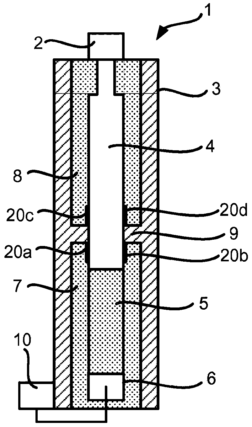
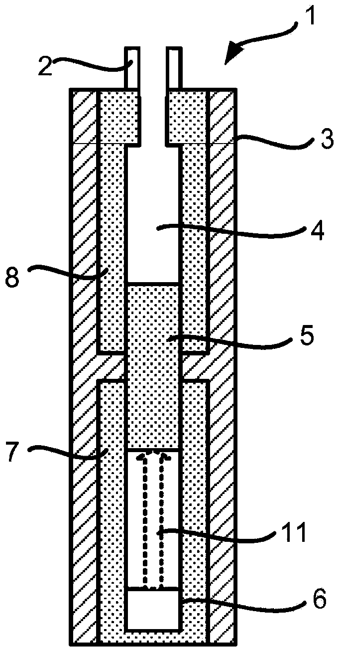
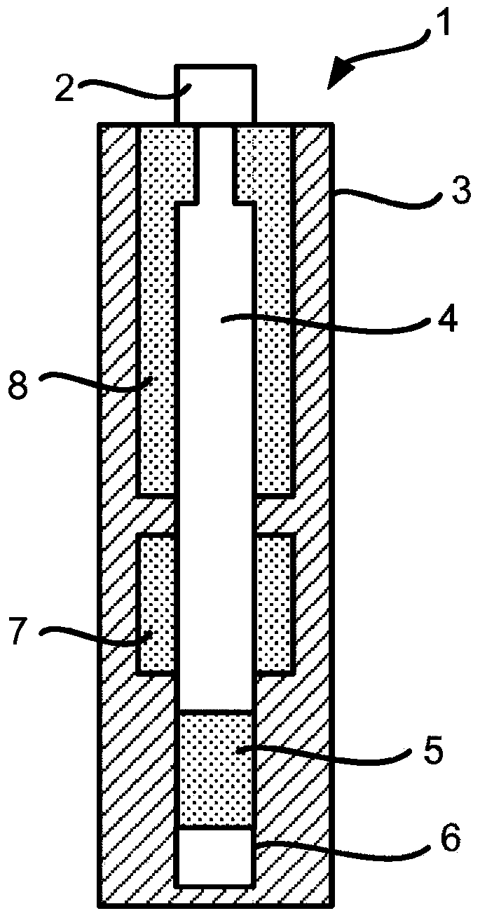
[0023] Figure 1-10 Different embodiments of a bypass switch assembly 1 for semiconductor modules are illustrated and may generally be denoted as a short circuit device. Figure 17-19 Schematically illustrates where the Figure 1-10 Any one of the illustrated bypass switch assemblies for a modular multilevel converter. The bypass switch assembly 1 can therefore preferably be used to exti...


PUM


Abstract

A mechanical switch in the form of a bypass switch assembly is arranged between two electrical conductors (busbars) and stays open during normal operation. When a cell fault happens, the fault and bypass information is transmitted to an actuator (acting as a trigger circuit) which activates inter alia a gas generator producing huge volume of gas in a very short time. The gas pressure pushes a movable member to bridge the two electrical conductors with ultrafast speed.

Description

technical field [0001] The invention relates to a bypass switch assembly for a semiconductor module. Background technique [0002] In contrast to the more common AC system, in a high voltage direct current (HVDC) power transmission system, direct current (DC) is used for the backbone transmission of power. A flexible alternating current transmission system (FACTS) is a system that includes static equipment for alternating current (AC) transmission of electrical energy. FACTS aims to improve controllability and increase the power delivery capability of the network. It is usually a system based on power electronics. [0003] An arc fault can generally be described as a high power discharge between two or more conductors. This discharge typically converts to heat that can damage the insulation of the wires and potentially cause an electrical fire. These arc faults range in current from a few amperes up to hundreds of thousands of amperes and are highly variable in intensity...

Claims


Application Information

Patent Timeline
IPC IPC(8): H01H39/00
CPCH01H39/004H01H33/26H01H33/905H01H33/91H01H2033/906H01H2033/912
Inventor A·奥伯格F·奇门托秦健王立伟O·杰普森
Owner HITACHI ENERGY SWITZERLAND AG
Why Eureka
Try Eureka