Vacuum quantifying tank

A quantitative tank and vacuum technology, applied in the field of vacuum quantitative tank, can solve the problems affecting the quality of castings, oxidation and slag inclusion, etc., and achieve more regular motion trajectory, stable gas flow and stable driving.

Active Publication Date: 2015-02-18
ANHUI OURUIDA ELECTRICAL APPLIANCE TECH
View PDF9 Cites 9 Cited by
  • Summary
  • Abstract
  • Description
  • Claims
  • Application Information

AI Technical Summary

Problems solved by technology

The products produced in this way will inevitably have oxidation and slag inclusions, which will affect the quality of castings

Method used


Image

  • Vacuum quantifying tank
  • Vacuum quantifying tank
  • Vacuum quantifying tank

Examples


Embodiment Construction

[0029] In order to make the object, technical solution and advantages of the present invention clearer, the present invention will be further described in detail below in conjunction with the accompanying drawings.

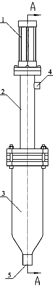
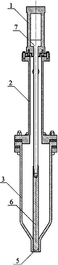
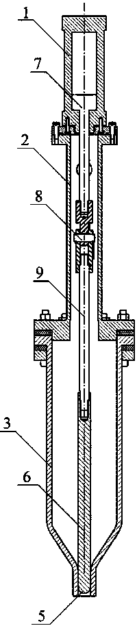
[0030] see figure 1 and figure 2 , figure 1 and figure 2 The first embodiment of the vacuum quantitative tank of the present invention is shown. The vacuum quantitative tank includes a cylinder 1, a bearing seat 2 and a tank body 3 which are sequentially sealed and connected in series. The cavities of the bearing seat 2 and the tank body 3 are connected to form Vacuum chamber. The bearing seat 2 is provided with a vacuum port joint 4 to control the vacuum degree of the vacuum cavity. A tank opening 5 is provided at the bottom of the tank body 3 , and a valve core 6 for sealing the tank opening 5 is provided in the cavity of the tank body 3 . The piston rod 7 inside the cylinder 1 is connected to the valve core 6, and the piston rod 7 drives the valve core 6...


PUM


Abstract

The invention discloses a vacuum quantifying tank which comprises a cylinder, a bearing seat and a tank body which are sequentially connected in series in a sealed manner, wherein the cavities of the bearing seat and the tank body are communicated to form a vacuum cavity; a vacuum port connector is arranged on the bearing seat, so that the vacuum degree of the vacuum cavity is controlled; a tank hole is formed in the bottom of the tank body; a valve core for sealing the tank hole is arranged inside the cavity of the tank body; the piston rod inside the cylinder is connected with the valve core; the piston rod drives the valve core to move upwards and downwards so as to control the tank hole to be opened and closed. By adopting the vacuum quantifying tank, automatic sucking and automatic pouring of stoste are achieved by controlling the vacuum degree of the vacuum cavity and the working state of the cylinder in the vacuum quantifying tank, the stoste can be conveyed in a sealed manner, the cleanliness degree is high, and the stoste is effectively prevented from being oxidized.

Description

technical field [0001] The invention relates to a device for automatically extracting materials, in particular to a vacuum quantitative tank. Background technique [0002] At present, the feeding manipulator of the die-casting machine uses a spoon to scoop the material from the upper liquid level of the holding furnace, and scoops the raw material from the holding furnace to the die-casting machine, which inevitably produces defects. One is floating on the liquid surface. The second is that the slurry is oxidized by air. The products produced in this way inevitably have oxidation and slag inclusions, which affect the quality of castings. Contents of the invention [0003] The technical problem to be solved by the present invention is to provide a vacuum quantitative tank with a simple structure, which can realize the automatic extraction and automatic pouring of the stock solution, has high sealing performance, and can effectively ensure the cleanliness of the stock solut...

Claims


Application Information

Patent Timeline
Patent Type & Authority Applications(China)
IPC IPC(8): B22D17/30
CPCB22D17/30
Inventor 陈凌杰吕国锋
Owner ANHUI OURUIDA ELECTRICAL APPLIANCE TECH
Why Eureka
Try Eureka