Blowout prevention oil well pump for oil field

An oil pumping and blowout prevention technology, which is applied to variable displacement pump components, pumps, and components of pumping devices for elastic fluids, etc., can solve the problems of high oil production cost, low oil production efficiency, intermittent oil production, etc. Achieve the effect of improving safety and stability, prolonging service life, and protecting blowout preventers

Inactive Publication Date: 2015-02-18
HANGZHOU HELLER SCI & TECH
View PDF0 Cites 7 Cited by
  • Summary
  • Abstract
  • Description
  • Claims
  • Application Information

AI Technical Summary

Problems solved by technology

[0002] In the process of oil production in the oil field, because the downhole formation pressure is higher than the upper liquid column pressure, the crude oil will overflow the wellhead and flow to the ground during the process of lifting and lowering the tubing, causing pollution to the environment, and there are certain safety hazards
[0003] With the development of science and technology, various oil well pumps begin to appear in the oil production process of oil fields, but there are some shortcomings in the oil well pumps in the prior art: 1, because it is a single plunger type design, there will be discontinuity in the oil production process Oil recovery cannot achieve continuous oil recovery, so the efficiency of oil recovery is low and the cost of oil recovery is high; 2. Because there is only one oil outlet, the oil output efficiency is low; 3. There is no blowout prevention device, which is easy to cause leakage during oil recovery; 4. Because there is no The filter device, the impurity particles in the collected crude oil are easy to block the oil well pump, or cause wear to the inside of the oil well pump, reducing the service life of the oil well pump

Method used


Image

  • Blowout prevention oil well pump for oil field
  • Blowout prevention oil well pump for oil field
  • Blowout prevention oil well pump for oil field

Examples


Embodiment Construction

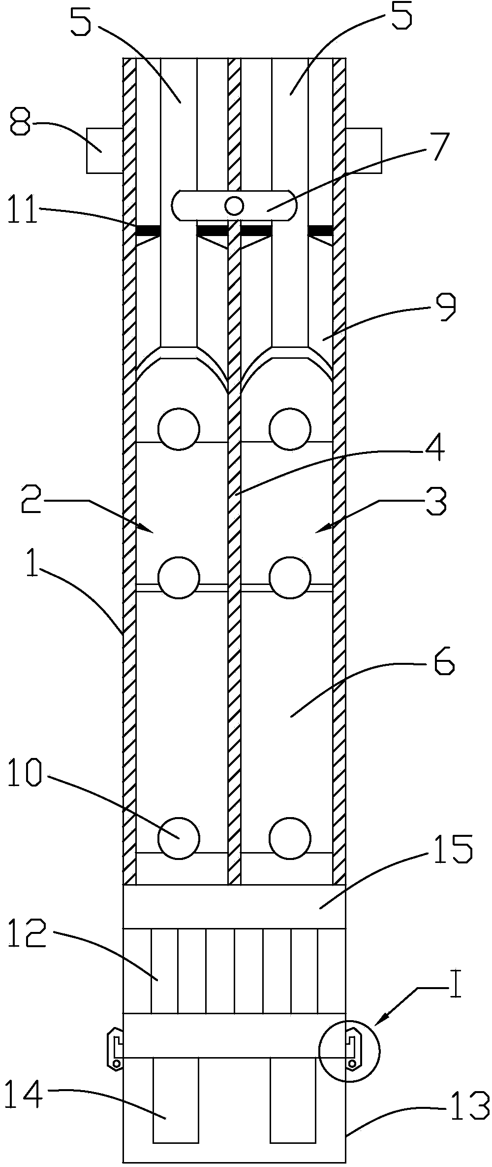
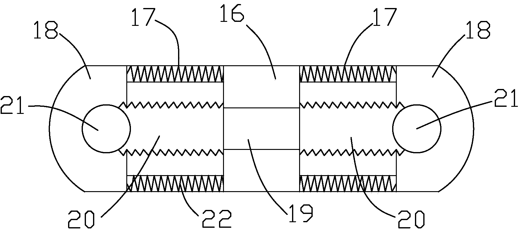
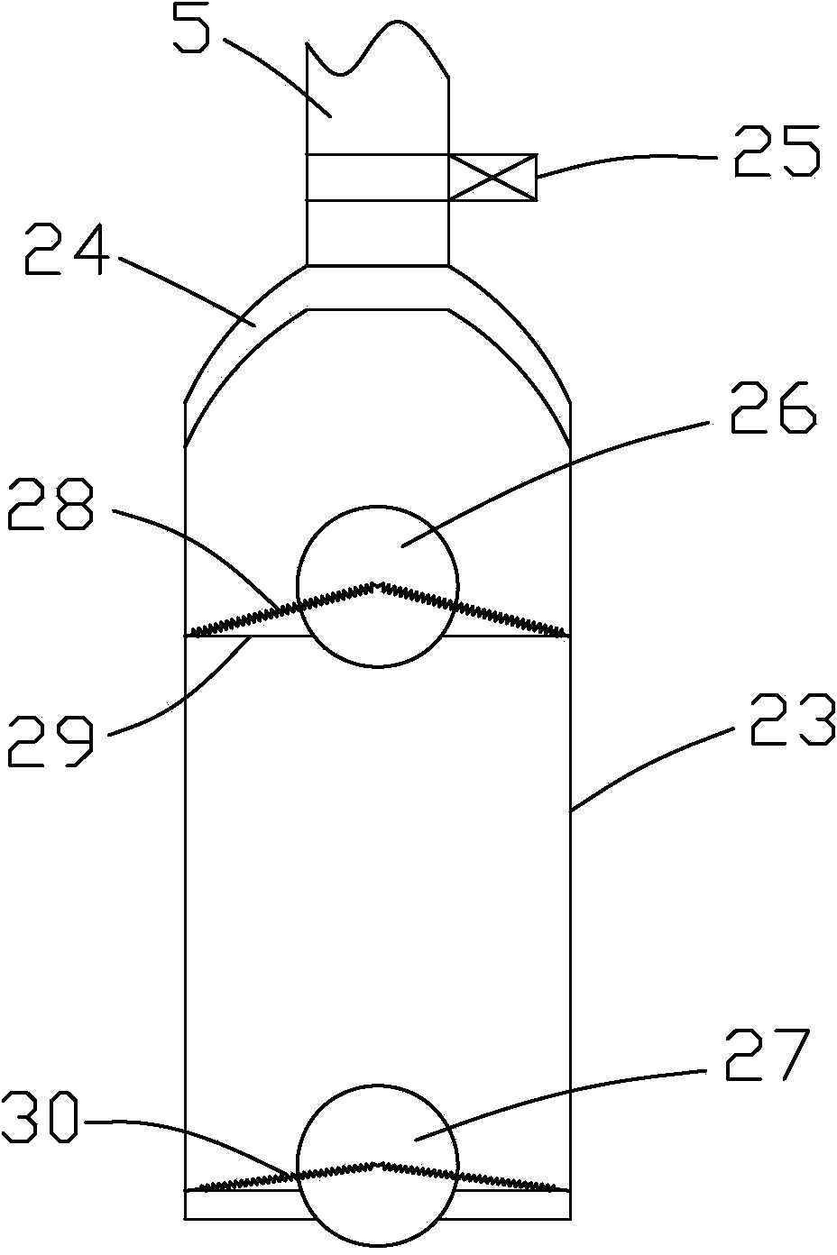
[0030] Such as Figure 1 to Figure 7As shown, it is a blowout prevention type oil well pump for oil field according to the present invention. The blowout prevention type oil well pump includes a pump body 1, and the upper end of the pump body 1 is provided with a mounting ring 8, which can make the installation of the pump body 1 firmer and more stable. , to prevent the pump body 1 from shaking during the oil pumping process, which improves safety. The pump body 1 is provided with an oil pumping mechanism and a blowout prevention device 12. The blowout prevention device 12 is located below the oil pumping mechanism. The oil pumping mechanism includes the first An oil pumping part and a second oil pumping part, a partition plate 4 is arranged between the first oil pumping part and the second oil pumping part, and the first oil pumping part includes a first oil pumping device 2, an oil pipe 6 and a pump barrel 9 , the second oil pumping part includes a second oil pumping device ...


PUM


Abstract

The invention discloses a blowout prevention oil well pump for an oil field, which comprises a pump body, wherein the pump body is internally provided with an oil pumping mechanism and a blowout prevention device; the oil pumping mechanism comprises a first oil pumping part and a second oil pumping part; the second oil pumping part comprises a second oil pumping device, an oil pipe and a pump cylinder; the first oil pumping device and the second oil pumping device comprise plungers and valve rods; oil-collecting hoods are arranged at the tops of the plungers; a connection bracket is arranged between every two adjacent valve rods and comprises a rotation support block, a telescopic connecting rod and a locating block; and the blowout prevention device comprises a housing; the housing is internally provided with a one-way guide plate; a buffer plate is arranged on the one-way guide plate; and an oil nipple and a filter screen are arranged at the bottom of the pump body. The oil recovery efficiency of the oil well pump is improved, continuous oil recovery is realized, simultaneous oil production of the double valve rods is realized, the oil production efficiency is improved, the oil recovery cost is lowered, and the economic benefit is significant.

Description

technical field [0001] The invention relates to a spray-proof oil well pump used in oil fields. Background technique [0002] In the process of oil production in the oil field, because the downhole formation pressure is higher than the upper liquid column pressure, the crude oil will overflow the wellhead and flow to the ground during the process of pulling out the tubing, causing pollution to the environment, and there are certain safety hazards. [0003] With the development of science and technology, various oil well pumps begin to appear in the oil production process of oil fields, but there are some shortcomings in the oil well pumps in the prior art: 1, because it is a single plunger type design, there will be discontinuity in the oil production process Oil recovery cannot achieve continuous oil recovery, so the efficiency of oil recovery is low and the cost of oil recovery is high; 2. Because there is only one oil outlet, the oil output efficiency is low; 3. There is ...

Claims


Application Information

Patent Timeline
Patent Type & Authority Applications(China)
IPC IPC(8): F04B47/00F04B53/20F04B53/10F04B53/00
Inventor 刘廷鹏连宏宾建军张涧
Owner HANGZHOU HELLER SCI & TECH
Why Eureka
Try Eureka