Strain gauge and methods for manufacturing and mounting strain gauge

A manufacturing method and technology of strain gages, which are applied in electromagnetic measuring devices, electric/magnetic solid deformation measurement, etc., can solve the problem of high technical level requirements of the personnel installing strain gages, inability to achieve high precision, long-term testing, and installation of strain gages. Time and other issues, to achieve the effect of high test accuracy, high strength and simple structure

Active Publication Date: 2015-02-18
中航电测仪器(西安)有限公司
View PDF6 Cites 17 Cited by
  • Summary
  • Abstract
  • Description
  • Claims
  • Application Information

AI Technical Summary

Problems solved by technology

Using the existing adhesive strain gauge to measure the stress and strain of the measured component, the installation method is complicated, the required conditions are harsh, the technical

Method used


Image

  • Strain gauge and methods for manufacturing and mounting strain gauge
  • Strain gauge and methods for manufacturing and mounting strain gauge
  • Strain gauge and methods for manufacturing and mounting strain gauge

Examples


Embodiment Construction

[0032] The present invention will be further described in detail below in conjunction with the accompanying drawings, which are explanations rather than limitations of the present invention.

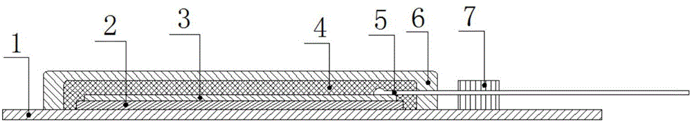
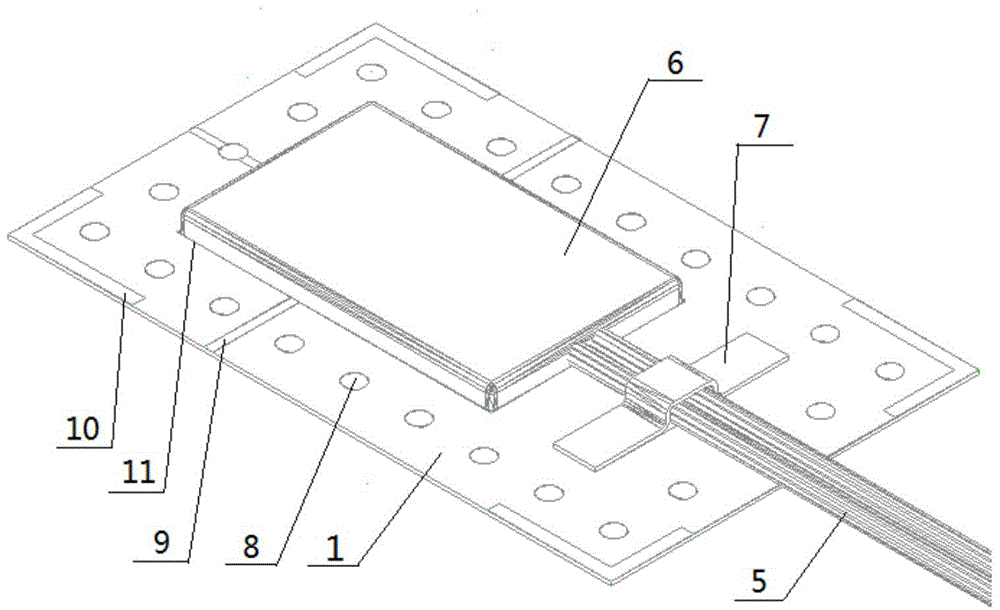
[0033] A kind of strain gauge of the present invention, as figure 1 As shown, it includes a metal base body 1, an adhesive layer 2, a resistance strain gauge 3, a moisture-proof layer 4, a signal lead 5 and a protective layer 6; the resistance strain gauge 3 is fixedly installed on the metal base body 1 through the adhesive layer 2 ; The signal lead 5 is electrically connected to the pad of the resistance strain gauge 3 and drawn; the moisture-proof layer 4 is coated on the surface of the resistance strain gauge 3, and its coverage area is greater than the surface area of ​​the resistance strain gauge 3, and the coating edge of the moisture-proof layer 4 is fixed on the surface of the resistance strain gauge 3. On the metal base body 1; the protection layer 6 is coated on the surface of ...


PUM

PropertyMeasurementUnit
Thicknessaaaaaaaaaa

Abstract

The invention provides a strain gauge which is quick to mount, high in test accuracy, high in resistance to heat and humidity, high in stability and suitable for stress strain test of medium-sized and large-sized metal components, and methods for manufacturing and mounting the strain gauge. The strain gauge comprises a metal base body, an adhesive layer, a resistance strain gauge, a moisture-proof layer, a signal lead and a protective layer, wherein the resistance strain gauge is fixedly mounted on the metal base body by virtue of the adhesive layer; the signal lead is electrically connected with a bonding pad of the resistance strain gauge and is led out; the moisture-proof layer coats the surface of the resistance strain gauge; the protective layer coats the surface of the moisture-proof layer. The manufacturing method comprises the following steps: (a) adhering the resistance strain gauge to the metal base body by virtue of an adhesive; (b) leading the signal lead out of the bonding pad of the resistance strain gauge; (c) forming the moisture-proof layer on the surface of the resistance strain gauge by virtue of a moisture-proof adhesive, wherein the coverage area of the moisture-proof layer is greater than that of the resistance strain gauge; (d) forming the protective layer on the surface of the moisture-proof layer by virtue of a protective adhesive, wherein the coverage area of the protective layer is greater than that of the moisture-proof layer. During mounting, the strain gauge is fused and welded on a measured metal component by virtue of spot welding equipment.

Description

technical field [0001] The invention relates to a strain gauge and its manufacture, in particular to a welded strain gauge and its manufacturing and installation method. Background technique [0002] At present, in the field of strain electrical measurement, stick-type resistance strain gauges are generally installed on the surface of the measured component to measure the stress and strain conditions on the surface of the measured component, and then directly or indirectly deduce the deformation of the measured component through the measurement results. other related parameters. Adhesives are used during the installation of stick-on strain gages, which can be divided into two categories: room temperature curing adhesives and high temperature curing adhesives. The characteristics of room temperature curing adhesives are easy to use, low cost, and easy to obtain, but their humidity resistance and long-term stability are relatively poor, which is suitable for general stress an...

Claims


Application Information

Patent Timeline
IPC IPC(8): G01B7/16
Inventor 晏志鹏任博哲熊英张勋赵家辉刘旭
Owner 中航电测仪器(西安)有限公司
Why Eureka
Try Eureka