
Rail vehicle collision experiment platform and rail vehicle collision experiment method

A crash test and rail vehicle technology, which is applied in the field of rail transit vehicle crash tests, can solve the problems of low speed control accuracy, difficult switching control, sensitive response, etc., to improve speed control accuracy, save required space, and small space Effect

Active Publication Date: 2015-02-18
CRRC QINGDAO SIFANG CO LTD
View PDF9 Cites 52 Cited by
  • Summary
  • Abstract
  • Description
  • Claims
  • Application Information

AI Technical Summary

Problems solved by technology

In this detection process, the real locomotive is used as the power source to drive. Since the locomotive needs manual operation, the operator has a lag in the operation of the train after receiving information such as speed. At the same time, the design function of the locomotive itself is to drag Passenger cars or freight cars are running normally, so the response sensitivity of the locomotive to the acceleration, deceleration or braking system of the operation is low, and its acceleration and braking processes cannot respond sensitively at important time and speed nodes, and it is difficult to achieve in a short control window period Precise Conversion Control
Therefore, in the prior art, the speed accuracy of the rail vehicle crash test completed by using the real rail vehicle including the locomotive as the power source is low, and the detection data cannot be obtained accurately
[0005] In the above-mentioned prior art, the low accuracy of speed control of the test vehicle during the rail vehicle crash test is a technical problem currently to be solved by those skilled in the art

Method used


Image

  • Rail vehicle collision experiment platform and rail vehicle collision experiment method
  • Rail vehicle collision experiment platform and rail vehicle collision experiment method

Examples


Embodiment Construction

[0042] The core of the invention is to provide a rail vehicle crash test platform and a rail vehicle crash test method. Through the application of the invention, the accuracy of speed control of the test vehicle during the rail vehicle collision test will be significantly improved.

[0043] The following will clearly and completely describe the technical solutions in the embodiments of the present invention with reference to the accompanying drawings in the embodiments of the present invention. Obviously, the described embodiments are only some, not all, embodiments of the present invention. Based on the embodiments of the present invention, all other embodiments obtained by persons of ordinary skill in the art without making creative efforts belong to the protection scope of the present invention.

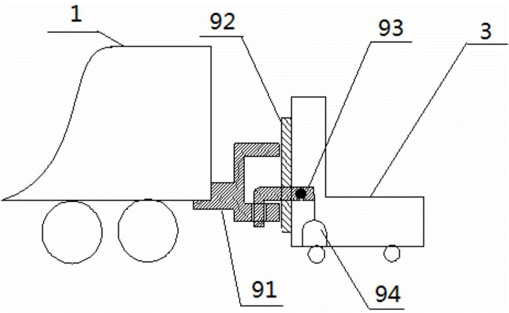
[0044] Please refer to figure 1 and figure 2 , the following specific implementation will compare figure 1 and figure 2 Discuss.

[0045] As shown in the figure, the test v...


PUM


Abstract

The invention relates to the technical field of rail traffic vehicle collision experiments, in particular to a rail vehicle collision experiment platform and a rail vehicle collision experiment method. By applying a driving motor, a braking motor, a detector and a controller, automated speed monitoring, accelerating and braking are realized in the process of a rail traffic vehicle collision experiment; especially by arranging the braking motor, braking for deceleration can be realized accurately when acceleration needs to be stopped. In the prior art, an actual locomotive is controlled through experimenting personnel to speed up a test vehicle in the process of the rail traffic vehicle collision experiment, time delay is generated in speed data receiving response and locomotive operation through artificial operation, and the actual locomotive cannot reach experiment accuracy requirements on system response sensitivity to acceleration and parking. Compared with the prior art, the rail vehicle collision experiment platform and the rail vehicle collision experiment method have the advantage that accuracy on speed control of the test vehicle in the process of the rail traffic vehicle collision experiment is improved remarkably. In addition, a long experiment rail needed for locomotive acceleration is avoided, and experiment space is saved.

Description

technical field [0001] The invention relates to the technical field of rail vehicle collision tests, in particular to a rail vehicle collision test bench and a rail vehicle collision test method. Background technique [0002] With the rapid development of the rail transit industry since my country entered the 21st century, the manufacturing technology of rail vehicles including trains and subways has been continuously improved. Among them, among the test methods based on safety and other performance requirements, the most effective and realistic test method is to conduct crash tests on real rail vehicles. [0003] In recent years, for the purpose of obtaining various real data, in the actual vehicle crash test of rail vehicles, the speed accuracy of the control test vehicle is required to be higher and higher. Therefore, the improvement of velocity accuracy during rail vehicle crash tests becomes a design goal. [0004] In the existing rail vehicle crash test, the test veh...

Claims


Application Information

Patent Timeline
IPC IPC(8): G01M7/08G01M17/08
Inventor 刘志祥王万静张志强陈一萍王伟华
Owner CRRC QINGDAO SIFANG CO LTD
Learn More