Motor speed control circuit

A speed control, speed voltage technology, applied in the direction of DC motor speed/torque control, single-phase motor control, AC motor control, etc., to achieve the effect of improving accuracy

Inactive Publication Date: 2009-08-05
SANYO ELECTRIC CO LTD
View PDF7 Cites 0 Cited by
  • Summary
  • Abstract
  • Description
  • Claims
  • Application Information

AI Technical Summary

Problems solved by technology

At this time, based on Figure 11 The logic shown produces the defect that although the motor drive circuit 11 receives the command to run the motor 1 at full speed, it acts in the direction of stopping the motor 1.

Method used


Image

  • Motor speed control circuit
  • Motor speed control circuit
  • Motor speed control circuit

Examples


Embodiment Construction

[0027]

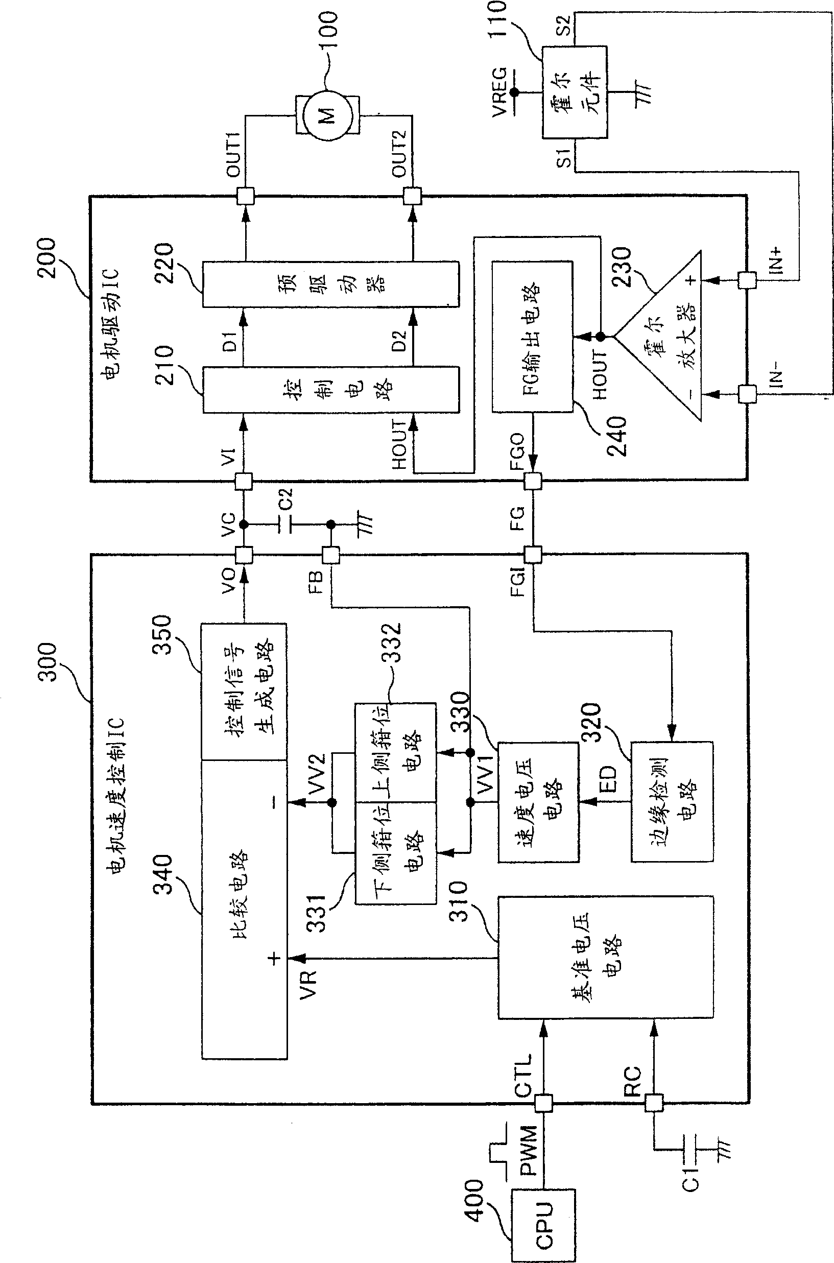
[0028] Appropriate reference Figure 2 to Figure 9 ,based on figure 1 A configuration example of the motor speed control system of the present invention will be described.

[0029] figure 1 The motor speed control system shown includes: a motor 100 to be controlled, a motor driver IC 200 ("first circuit" of the present invention), and a motor speed control IC 300 ("second circuit" of the present invention). That is, the "motor speed control circuit" of the present invention is a case of a two-chip structure in which the motor driver IC 200 and the motor speed control IC 300 are respectively integrated on one chip. In addition, the "motor speed control circuit" of the present invention may be a case where the motor driver IC 200 and the motor speed control IC 300 are integrated on one chip.

[0030] The motor 100 is a so-called single-phase motor having a single-phase drive coil, and a so-called Hall motor in which a Hall element 110 is fixed to a stator. In ad...


PUM


Abstract

A motor speed control circuit which controls a rotational speed of a motor by controlling an amount of current flowing through a drive coil of the motor. The control circuit comprises a reference voltage circuit that generates a reference voltage corresponding to a speed-specifying signal inputted to specify the rotational speed of the motor; a speed voltage circuit that generates a speed voltage corresponding to an actual rotational speed of the motor; a clamp circuit that limits the level of the speed voltage generated by the speed voltage circuit; a comparator that has the reference voltage generated by the reference voltage circuit and the speed voltage limited in level by the clamp circuit applied thereto and compares the two; and a control signal generator that generates and outputs a control signal for controlling the amount of current flowing through the drive coil based on the comparing result of the comparator.

Description

technical field [0001] The present invention relates to motor speed control circuits. Background technique [0002] Various electronic devices have a heat generating body that generates heat when the electronic device is in operation, and a fan motor is generally provided to cool the heat generating body. For example, in personal computers, servers, etc., the operating frequency of the CPU is increasing year by year, and the amount of heat generated by the CPU is increasing accordingly. Therefore, in a personal computer, a server, or the like, a fan motor for cooling the CPU and a motor drive circuit for driving the fan motor are generally provided. [0003] In addition, as the speed control method of the fan motor, for example, proposed as Figure 10 The speed servo control method combined with the PWM driving method shown (for example, refer to the following patent document 1). [0004] More specifically, the rotational speed detection signal obtained from the pulse gene...

Claims


Application Information

Patent Timeline
Patent Type & Authority Patents(China)
IPC IPC(8): H02P23/14H02P27/00H02P6/06H02P6/08H02P6/17H02P6/26
CPCH02P7/2913H02P7/282H02P6/06
Inventor 扇野广一郎原岛崇
Owner SANYO ELECTRIC CO LTD
Why Eureka
Try Eureka