Eureka AIR delivers breakthrough ideas for toughest innovation challenges, trusted by R&D personnel around the world.

A control method of electronically controlled silicon oil fan clutch

A technology of clutch control and fan, which is applied in the control of coolant flow, machine/engine, engine cooling, etc. It can solve the problems of inability to realize fan multi-level speed regulation, poor cooling effect, loud noise, etc., and solve the problem of OFF state Insufficient cooling efficiency, low noise, and high control accuracy

Active Publication Date: 2020-12-08
XIAN AVIATION COMPUTING TECH RES INST OF AVIATION IND CORP OF CHINA
View PDF6 Cites 0 Cited by
  • Summary
  • Abstract
  • Description
  • Claims
  • Application Information

AI Technical Summary

Problems solved by technology

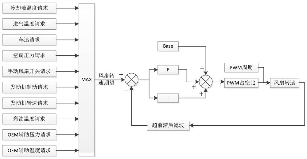
[0004] Aiming at the problem that the existing ON / OFF switch control method cannot realize the multi-level speed regulation of the fan, and only considers the coolant temperature and the intake air temperature, and does not fully consider the vehicle speed, air-conditioning pressure, manual fan switch, engine braking, engine speed, Fuel temperature, OEM (Original Equipment Manufacturer) auxiliary pressure, OEM auxiliary temperature and other factors lead to poor cooling effect, high energy consumption, and high noise. The invention provides an electronically controlled silicon oil fan clutch control method

Method used


Image

  • A control method of electronically controlled silicon oil fan clutch

Examples


Embodiment Construction

[0066] The embodiment of the present invention is illustrated by examples below. What this example uses is a six-cylinder heavy truck engine electronic controller. Burn domestic software in the controller. The implementation steps are as follows:

[0067] Step 1: Calculate the expected value of the fan speed under the current engine operating condition according to the influencing factors of the engine temperature: the influencing factors include coolant temperature, intake air temperature, vehicle speed, air-conditioning pressure, manual fan switch, engine braking, engine speed, and fuel temperature , OEM auxiliary pressure, OEM auxiliary temperature;

[0068] Step 1.1: Calculate the desired fan speed request percentage corresponding to each influencing factor, and select the largest desired fan speed request percentage as the desired fan speed percentage Rqst_Rt;

[0069] In this embodiment, the largest expected fan speed request percentage among the expected fan speed reque...


PUM


Abstract

The invention relates to a control method of an electronic control silicone oil fan clutch. The method mainly includes the following steps of firstly, calculating the expected value of the rotating speed of a fan under the current working conditions of an engine according to an influence factor of the temperature of the engine; secondly, calculating the PWM duty cycle Duty_Cyc of the control overthe rotating speed of the fan in the current cycle; thirdly, sending the PWM cycle calibrated in advance and the PWM duty cycle Duty_Cyc of the control over the rotating speed of the fan in the current cycle to a PWM controller through an ECM, and adjusting the amount of silicone oil in a working cavity of the electronic control silicone oil fan clutch through the PWM controller to realize one time of adjustment of the rotating speed of the fan; and fourthly, executing the first step, the second step and the third step again to obtain the PWM duty cycle Duty_Cyc of the control over the rotating speed of the fan in each cycle, thereby realizing multi-stage adjustment of the rotating speed of the fan. By means of the method, the precision of the control over the rotating speed of the fan ishigh, noise is low, energy consumption is reduced, more oil is saved by the engine, and the fuel oil economical performance is greatly improved.

Description

technical field [0001] The invention belongs to the field of electronic function control for electronically controlled engines, and relates to an electronically controlled silicon oil fan clutch control method. Background technique [0002] The engine is the heart of the car, and its working status directly affects the power, fuel economy and emissions of the vehicle. With the rapid development of the automobile industry, engine functions are becoming more and more complex, including more and more accessories, and engine power is increasing, making the engine more vulnerable to high temperature threats. A good cooling system fan control method can not only ensure that the engine runs at the optimum temperature and stay away from the threat of high temperature, but also is one of the most effective measures to reduce the engine's ineffective energy consumption and improve the vehicle's economy and power. With the increasing demand of users for low emission, low noise and fue...

Claims


Application Information

Patent Timeline
Patent Type & Authority Patents(China)
IPC IPC(8): F01P7/04
CPCF01P7/04F01P2050/22
Inventor 马振华高博谭琪璘王瑞于正同
Owner XIAN AVIATION COMPUTING TECH RES INST OF AVIATION IND CORP OF CHINA
Why Eureka
Eureka Blog
Learn More