
Adaptive beam forming method based on 1 norm constraint

An adaptive beam and norm technology, applied in the direction of radio wave measurement systems, instruments, etc., can solve problems such as array manifold mismatch, affecting beam performance, steering vector mismatch, etc., and achieve good robustness

Inactive Publication Date: 2015-02-18
XIDIAN UNIV
View PDF2 Cites 7 Cited by
  • Summary
  • Abstract
  • Description
  • Claims
  • Application Information

AI Technical Summary

Problems solved by technology

However, in practical problems, the steering vector does not match, the covariance matrix is ​​inaccurate, and the received data contains strong desired signals, etc., which will affect the performance of beamforming.
[0003] Aiming at the deficiencies in the traditional beamforming method, scholars have proposed a robust adaptive beamforming method based on Diagonal loading (DL), which has the disadvantages of array manifold mismatch and small sample environment. Very good robust effect, but when there is a desired signal in the received signal, signal cancellation will occur, resulting in a serious decline in algorithm performance
The Worst-case BF algorithm is a robust BF method based on the worst environment. This method assumes that the array error belongs to a spherical uncertain set and constrains the target steering vector. However, when there is signal cancellation, the performance of the algorithm is decline
The subspace method is another robust adaptive beamforming method. This method first estimates the interference-plus-signal subspace, and then projects the steering vector of the target signal to obtain adaptive weights. Known number of interferers and less effective at low SNR

Method used


Image

  • Adaptive beam forming method based on 1 norm constraint
  • Adaptive beam forming method based on 1 norm constraint
  • Adaptive beam forming method based on 1 norm constraint

Examples


Embodiment Construction

[0024] The present invention will be further explained below in conjunction with the drawings:

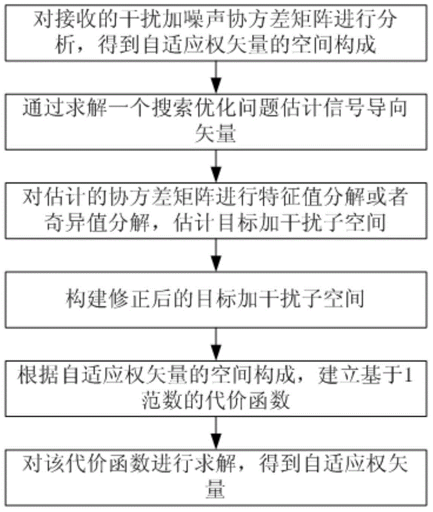
[0025] Reference figure 1 , Is a flowchart of the adaptive beamforming method based on 1-norm constraint of the present invention. The adaptive beamforming method based on 1-norm constraint includes the following steps:

[0026] Step 1. Use the radar receiving array to receive signals. The signals received by the radar receiving array include interference signals and target echo signals; the radar receiving array is a uniform linear array, and the number of elements of the radar receiving array is N. The radar receiving The array element spacing is d, and the number of samples of the signal received by the radar receiving array is L.

[0027] The specific sub-steps are:

[0028] The far-field narrowband signal received by the radar receiving array is used, and the far-field narrowband signal received by the radar receiving array includes interference signals and target echo signals. In ...


PUM


Abstract

The invention belongs to the technical field of radar adaptive beam forming, and particularly relates to an adaptive beam forming method based on 1 norm constraint. The method includes the specific steps of receiving signals through a receiving array of radar, wherein the signals received through the receiving array of the radar include the interference signal and the target echo signal, and the receiving array of the radar is a uniform linear array; making e represent the error vector between a set target guide vector s and the estimation (please see the specifications) of the target guide vector; establishing an optimization model about the vector e, and solving the optimization model about the vector e so as to obtain the estimation (please see the specifications) of the target guide vector, wherein the estimation (please see the specifications) is equal to the sum of s and e; obtaining the estimation (please see the specifications) of the covariance matrix of the received signals received by the receiving array of the radar; making U represent the matrix composed of the feature vectors corresponding to all feature values of the estimation (please see the specifications) of the covariance matrix of the received signals; making the front k lines of the matrix U serve as target and interference sub-spaces (please see the specifications), wherein the formula of the target and interference sub-spaces is equal to the formula (please see the specifications); establishing the cost function based on the 1 norm constraint; solving the cost function based on the 1 norm constraint so as to obtain a vector beta; obtaining the adaptive weight vector W[opt], wherein W[opt] is equal to the product of the target and interference sub-spaces (please see the specifications) and beta.

Description

Technical field [0001] The invention belongs to the technical field of radar adaptive beamforming, and particularly relates to an adaptive beamforming method based on 1-norm constraint. Background technique [0002] Beam forming (BF) is a key technology in the field of array signal processing. In recent decades, it has been one of the hot issues of array signal processing, and it has been widely used in military and national economic fields such as radar, sonar, voice microphone, satellite communications, and seismic detection. The basic idea of ​​beamforming is: by weighting and summing the output of each element, the antenna array beam is "directed" to one direction, and the direction of arrival (Direction of arrival) is given to the steering position of the desired signal to obtain the maximum output power. ,DOA) estimate. Traditional beamforming refers to beamforming under the condition that the desired signal direction vector is accurately known and the corresponding covar...

Claims


Application Information

Patent Timeline
IPC IPC(8): G01S7/41
CPCG01S7/414
Inventor 冯大政蒋雨解虎侯瑞利
Owner XIDIAN UNIV
Learn More