Transformer coil and winding method thereof and automatic winding machine

A technology of transformer coils and automatic winding machines, which is applied in the direction of transformer/inductor coil/winding/connection, coil manufacturing, etc., which can solve the problems of large coil outer diameter direction, waste of wires, low degree of automation, etc., and achieve reduction Overall dimensions, reduced prefabrication man-hours, and improved production efficiency

Active Publication Date: 2015-02-18
SHANDONG YINGBO ELECTRIC POWER EQUIP
View PDF4 Cites 7 Cited by
  • Summary
  • Abstract
  • Description
  • Claims
  • Application Information

AI Technical Summary

Problems solved by technology

The disadvantages of the transformer coil or winding method are as follows: 1. The coil winding production efficiency is low; 2. It is necessary to manually prefabricate the interlayer cable paper according to the coil height, and the end insulation end ring must be manually prefabricated according to the coil size; 3. It cannot be layered The size of the interlayer voltage gradient places the number of layers of interlayer insulation, and the entire cable paper is used to wrap the waste material; 4. Due to the waste of coil insulation material and thickening of the insulation, the direction of the outer diameter of the coil becomes larger, further wasting the wire
To sum up, the current upper horizontal winding machine, automatic cable winding machine, etc. have a low degree of automation, and the waste of materials is serious. The transformer market in my country has a large capacity, which will cause a lot of waste every year.

Method used


Image

  • Transformer coil and winding method thereof and automatic winding machine
  • Transformer coil and winding method thereof and automatic winding machine
  • Transformer coil and winding method thereof and automatic winding machine

Examples


Embodiment 1

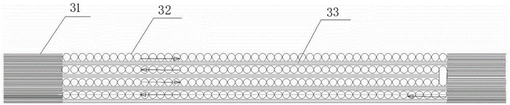
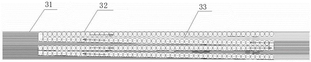
[0045] like figure 2 The embodiment of the present invention is a transformer coil, including the wire layer 33, the intervertebral insulation layer 32 between the two adjacent wire layers 33 and the end insulating layer 31, of which the thickness of the intervertebral insulation layer 32 follows the thickness of the layer 32.The voltage gradient of the two adjacent wire layer 33 increased and increased.The inter -layer insulation layer 32 and the end -end insulation layer 31 are made of stacking of the insulating paper belt, and the thickness of the thickness of the inter -layer insulation layer 32 changes with the turbine spacing of the insulator belt, and the thickness of the end insulation layer 31 is uniform.Among them, the intervertebral insulation layer 32 and end insulation layer 31 located on the same layer are made of continuous winding.

[0046]

Embodiment 2

[0048] The embodiment of the present invention provides a winding method of a transformer coil. The insulating layer is made of an insulation paper belt. The method of winding includes the following steps:

[0049] (1) Insulation paper belt first to complete the end -end insulation layer of the first elementary level;

[0050](2) Press the wires above the insulation paper belt. The two are winding at the same time.The end -insulation layer, cut off the insulation paper belt, the wire one -way winding of the wire to complete the wire layer;

[0051] (3) Continuous opposite winding of the wires, press the insulation paper belt below again, repeat the steps (2), and finally complete the end -layer intervertebral insulation layer, the end -end insulation layer and the last layer of the wire in turn.The layer is the transformer coil.

[0052] Among them, in the step (1), the insulation paper belt to the re -system to obtain the end -end insulating layer of the uniformity of the middle ...

Embodiment 3

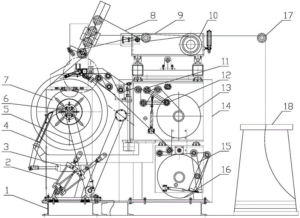
[0059] See image 3 As well as Figure 4 and Figure 5 , The present invention is an automatic winding machine, including the main axis 21 and the main axis of the driver's spindle 21 rotating the spindle of the main axis 21 with the spindle of the main axis.Motor 19 and the main axis reducer 20, the output shaft of the main axis reducer 20 drives the spindle 21; it also includes a wire winding mechanism set on the rack 1 and the insulating paper band winding mechanism.Linear driver mechanisms moved by block 9 and driving wires 9 horizontal moving. The wire activity block 9 is equipped with a wire plate 10 with a wire and a wire;14 High -level non -linear driver, insulation paper tape activity block 14 is set on the insulating paper band with insulating paper belt (the embodiments of the present invention include two insulation paper bands, insulation paper band A13 and insulation paper beltDisk B16); Insulation paper tape activity block 14 also has a pressure wheel mechanism that ca...


PUM


Abstract

The invention provides a transformer coil and a winding method thereof and an automatic winding machine. The transformer coil comprises lead wire layers, interlayer insulating layers positioned between every two adjacent lead wire layers and end part insulating layers, wherein the thicknesses of the interlayer insulating layers are increased along with the increase of the voltage gradient of the upper and lower adjacent lead wire layers. The transformer coil has the beneficial effects that an insulating paper band replaces a piece of whole insulating paper, so that automatic winding of lead wires and the insulating paper band is realized; furthermore, the thicknesses of the insulating layers are adjusted according to the voltage gradient between the adjacent lead wires, so that the prefabrication working time of an insulating material is shortened, the appearance size of the coil is reduced, the manufacturing cost of the coil is greatly lowered, and the production efficiency is improved.

Description

[0001] Technical field [0002] The invention involves the field of winding equipment technology, especially a transformer coil and its winding method, and automatic winding machines for winding transformer coils. [0003] Background technique [0004] The core of the electrical transformer is the coil of the transformer. The coils of the transformer are manufactured by the coil due to the large models and the coils. At present, the horizontal winding machine is artificially wrapped in China.Inter -layer insulation adopts a few layers of cable paper that is consistent with the height of the coil, or uses segmented insulation to artificially surround several layers. figure 1 The thickness of inter -layer insulation is the same.The disadvantages of the transformer coil or bypass method are as follows: 1. The coil winding production efficiency is low; 2. The cable paper is required by the coil height, and the insulating ring of the prefabricated end of the coil size must beThe numbe...

Claims


Application Information

Patent Timeline
IPC IPC(8): H01F27/32H01F41/12H01F41/06
Inventor 周来田
Owner SHANDONG YINGBO ELECTRIC POWER EQUIP
Why Eureka
Try Eureka