Flyback type non-optical-coupler thick film DC/DC switching power supply

A switching power supply and flyback technology, which is applied in the field of power electronics and microelectronics, can solve the problems of switching power supply index out-of-tolerance, increasing circuit complexity, affecting power supply reliability, etc., to improve reliability indicators and reduce layout Difficulty and requirements, the effect of light weight

Inactive Publication Date: 2015-02-18
程信羲
View PDF3 Cites 8 Cited by
  • Summary
  • Abstract
  • Description
  • Claims
  • Application Information

AI Technical Summary

Problems solved by technology

[0003] After the high-temperature life test of the optocoupler, the switching power supply index will be seriously out of tolerance, or even fail, thus seriously affecting the reliability of the power supply
[0004] Another more effective solution is to use the secondary side magnetic feedback isolation and control circuit, such as the technical solution published by the Chinese utility model patent application number: 201020662274.4, but this will increase the complexity of the circuit, increase the volume and increase the cost

Method used


Image

  • Flyback type non-optical-coupler thick film DC/DC switching power supply
  • Flyback type non-optical-coupler thick film DC/DC switching power supply
  • Flyback type non-optical-coupler thick film DC/DC switching power supply

Examples


Embodiment Construction

[0027] In order to make the object, technical solution and advantages of the present invention clearer, the present invention will be further described in detail below in conjunction with the accompanying drawings and embodiments. It should be understood that the specific embodiments described here are only used to explain the present invention, not to limit the present invention.

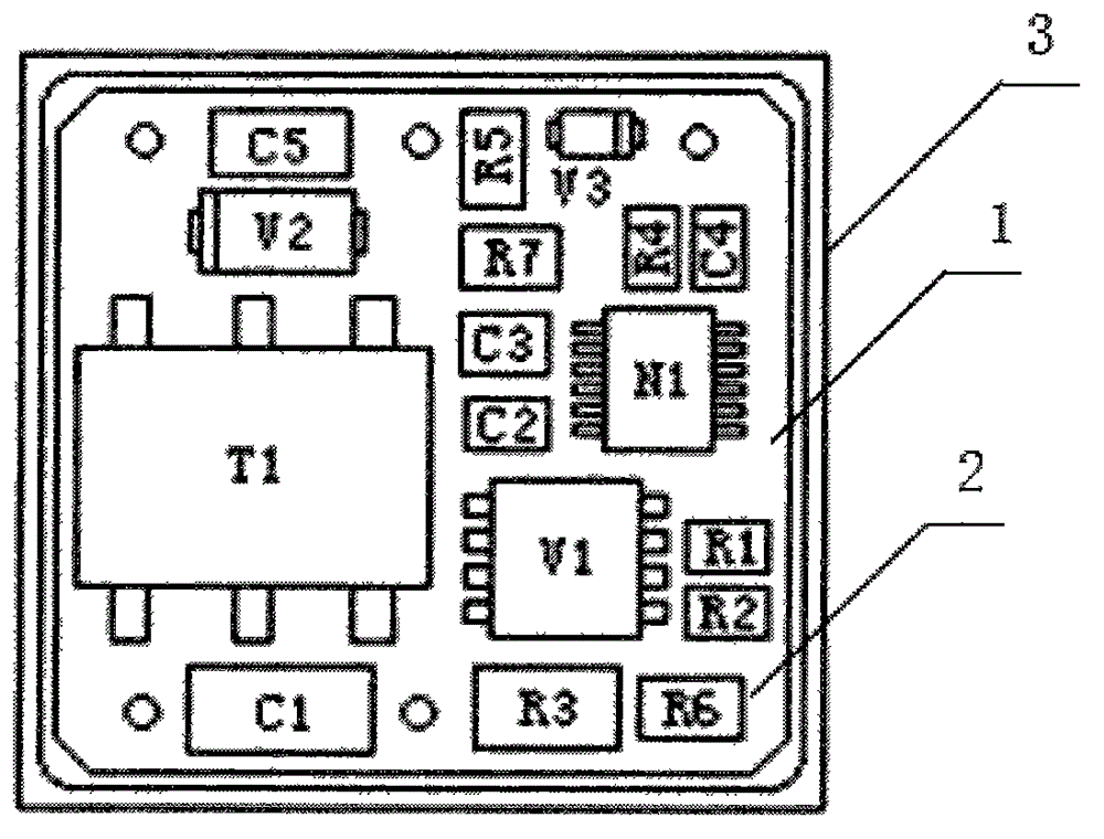
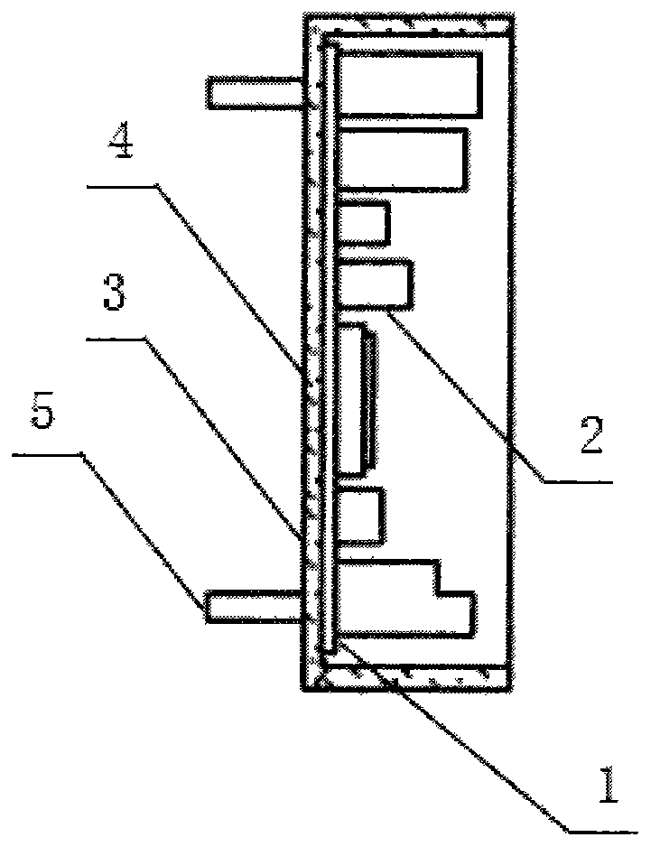
[0028] refer to figure 1 and figure 2 It can be seen that the flyback thick film DC / DC switching power supply without optocoupler, including copper clad Al 2 o 3 Ceramic substrate 1, SMT components 2, dual-in-line metal hermetic packaging shell 3, the dual-in-line metal hermetic packaging shell 3 is soldered to copper-clad Al 2 o 3 The back of the ceramic substrate 1, the SMT components 2 are soldered to the copper clad Al 2 o 3 The front of the ceramic substrate 1; the inside of the dual in-line metal hermetic packaging shell 3 is provided with a cavity, the cavity is filled with an inert g...


PUM


Abstract

The invention relates to the power electronic technology and the micro electronic technique and in particular relates to a flyback type non-optical-coupler thick film DC / DC switching power supply. The flyback type non-optical-coupler thick film DC / DC switching power supply comprises a copper-coated Al2O3 ceramic substrate, an SMT (surface mounting technology) device and a dual in-line type metal hermetic sealing shell, wherein the dual in-line type metal hermetic sealing shell is tin-soldered on the back surface of the copper-coated Al2O3 ceramic substrate, the SMT device is tin-soldered on the front surface of the copper-coated Al2O3 ceramic substrate, a cavity is formed inside the dual in-line type metal hermetic sealing shell and is filled with inert gas, pins are arranged on the bottom surface of the dual in-line type metal hermetic sealing shell, and a flyback type non-optical-coupler DC / DC circuit is arranged on the copper-coated Al2O3 ceramic substrate. The flyback type non-optical-coupler thick film DC / DC switching power supply overcomes the defect of high temperature life of a photoelectric coupler, the troubles of secondary magnetic isolation feedback complexity, the volume and the cost are avoided, and the flyback type non-optical-coupler thick film DC / DC switching power supply has the characteristics of simple circuit, good output characteristics, quick dynamic response, metal hermetic sealing, good heat dissipation property, and high reliability.

Description

technical field [0001] The invention relates to power electronic technology and microelectronic technology, in particular to a flyback type non-optocoupler thick film DC / DC switching power supply. Background technique [0002] Traditional flyback DC / DC switching power supplies mostly use optocouplers as isolation and control feedback components. As we all know, a photocoupler is made of a light-emitting diode and a phototransistor (or diode) through a fixed package, and its coupling efficiency is easily affected by temperature and time. [0003] After the high-temperature life test of the optocoupler, the switching power supply index will be seriously out of tolerance, or even fail, thus seriously affecting the reliability of the power supply. [0004] Another more effective solution is to use secondary side magnetic feedback isolation and control circuits, such as the technical solution disclosed in Chinese utility model patent application number: 201020662274.4, but this ...

Claims


Application Information

Patent Timeline
Patent Type & Authority Applications(China)
IPC IPC(8): H02M3/335
Inventor 程信羲
Owner 程信羲
Why Eureka
Try Eureka