
Hybrid aircraft

A technology for aircraft and internal combustion engines, which is applied in aircraft parts, hybrid vehicles, aircraft, etc., and can solve problems such as large fuel consumption of aircraft

Inactive Publication Date: 2015-02-18
SIEMENS AG
View PDF15 Cites 10 Cited by
  • Summary
  • Abstract
  • Description
  • Claims
  • Application Information

AI Technical Summary

Problems solved by technology

However, this leads to a correspondingly large fuel consumption of the aircraft

Method used


Image

  • Hybrid aircraft
  • Hybrid aircraft

Examples


Embodiment Construction

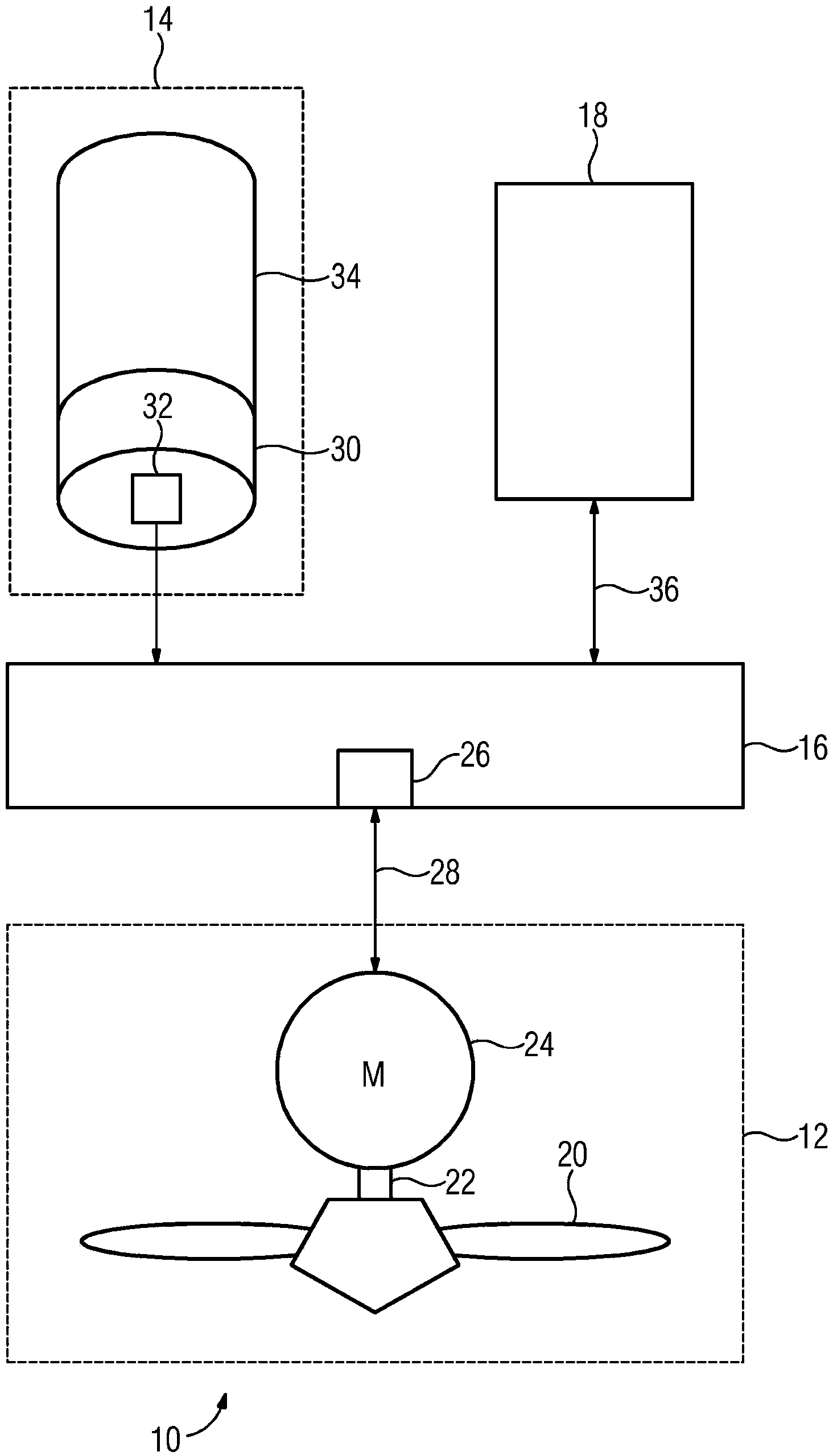
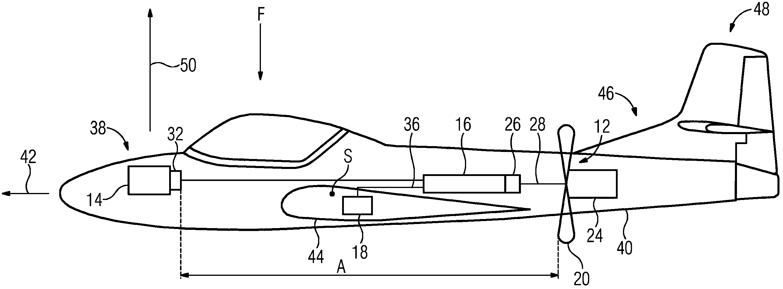
[0046] exist figure 1 An aircraft drive 10 is shown in , which has a propulsion generating unit 12 , an energy generating unit 14 , electronics for distributing the power, which is an electrical transmission device 16 , and a battery device 18 . The transmission device 16 can include a direct voltage intermediate circuit as well as rectifiers and inverters for converting electrical energy with the direct voltage intermediate circuit. Aircraft drive 10 can be embodied, for example, in a light aircraft. The propulsion generating unit 12 has a propeller 20 which is coupled via a shaft 22 to an electric motor 24 . The electric motor 24 rotates the shaft 22 and thus rotationally drives the propeller 20 . The electric motor 24 can additionally be coupled to the propeller 20 via a transmission.

[0047] The rotational speed and the torque generated by the electric motor 24 are set by the converter 26 in a manner known per se. The three-phase currents are set at variable frequenci...


PUM


Abstract

The invention relates to a hybrid aircraft (F). According to the invention, a suitable position for mounting an energy generation unit (14) in the aircraft is identified, said energy generation unit comprising an internal combustion engine (34) and an electric generator (30) that is coupled thereto via a shaft. Independently of the position of the energy generation unit (14), a position is also identified for a thrust generation unit (12) comprising an electric motor (24) and a propeller (20) that is coupled thereto via a shaft (22). When the aircraft (F) is built, the thrust generation unit (12) and the energy generation unit (14) are disposed in the positions identified therefor. The generator (30) is then coupled to the electric motor (24) via an electric transmission device (16).

Description

technical field [0001] The invention relates to a hybrid aircraft and a method for producing the aircraft. The aircraft has an internal combustion engine by means of which drive power can be generated for driving a propeller of the aircraft. Aircraft is understood in particular to mean an engine-driven rigid-wing aircraft. However, aircraft is also understood to mean, for example, rotorcraft machines (gyroplanes, helicopters) and powered gliders. Background technique [0002] In today's aircraft with a propeller drive, for example light aircraft, an internal combustion engine, for example a piston engine or a turbine engine, is rigidly coupled to the propeller via a shaft or via a transmission in order to drive it. Due to the mechanical coupling between the internal combustion engine and the propeller, an aircraft drive configured in this way is mounted centrally on the aircraft, mainly on the wings or on the fuselage tip. These positions have proven to be an advantageous...

Claims


Application Information

Patent Timeline
Patent Type & Authority Applications(China)
IPC IPC(8): B64C31/024B64D27/24B64D27/02
CPCB64C2201/044B64D27/24Y02T50/64B64C31/024B64C2201/048B64D2027/026B64C2201/042Y10S903/903Y02T50/60B64U50/11B64U50/12B64U50/19B64D27/026
Inventor 弗兰克·安东斯文·格迪加约翰内斯·沃伦贝格
Owner SIEMENS AG
Learn More