Composite vertical take-off/landing aircraft

A technology of vertical take-off and landing and aircraft, applied in the direction of vertical take-off and landing aircraft, aircraft, rotorcraft, etc., can solve the problems of hovering and unconventional maneuvering performance loss, easy to cause loss of control, tactical action troubles, etc.

Inactive Publication Date: 2015-02-25
吴建伟
View PDF0 Cites 24 Cited by
  • Summary
  • Abstract
  • Description
  • Claims
  • Application Information

AI Technical Summary

Problems solved by technology

The thick, short and thick rigid rotating wings fundamentally solve many problems that are difficult to solve with the slender flexible rotor blades, but compared with conventional helicopters, the hovering and unconventional maneuvering performance of these aircraft suffer a certain loss
The main technical problem of the CRW aircraft is the flight control problem during the conversion of the lift generation mechanism, which is likely to cause control cross-coupling; moreover, the fuselage is susceptible to severe airflow disturbances, and the airspeeds in two directions are superimposed and the wings are still When the rotor is in the rotating working state, the aircraft will generate a head-up moment that is difficult to recover, which can directly cause the aircraft to lose control
In fact, all the "rotor / wing" technologies (Rotor / Wing, RW) that are switched in the lift generation mechanism have control problems during the transition of the mechanism. Switching too fast can easily lead to loss of control. At the same time, the mechanism switching also has speed and height restrictions. It cannot be switched anytime and anywhere.
In combat, the requirements for switching time, altitude, and speed bring great trouble to tactical actions.

Method used


Image

  • Composite vertical take-off/landing aircraft
  • Composite vertical take-off/landing aircraft
  • Composite vertical take-off/landing aircraft

Examples


Embodiment Construction

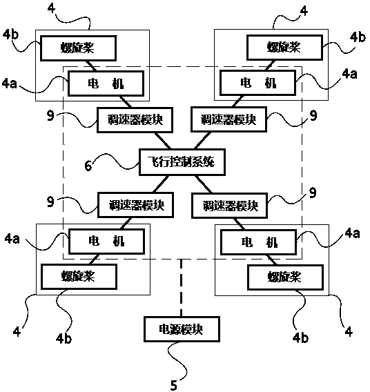
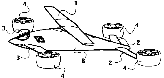
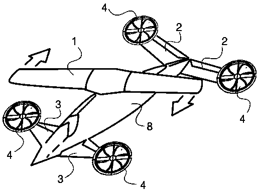
[0019] figure 2 The appearance structure diagram of a compound vertical take-off and landing aircraft of the present invention is shown, including a fuselage 8, a rotor / wing 1 that can be switched to a rotor state or a fixed wing state, and a locking device for locking the rotor / wing 1 , canard front wing 3, horizontal empennage 2, canard front wing 3 comprises left front wing, right front wing, and horizontal tail wing 2 comprises left empennage, right empennage; Wherein, this aircraft also comprises attitude control device; figure 1 Shown is a working principle diagram of the attitude control device of a composite vertical take-off and landing aircraft of the present invention, the attitude control device is composed of an attitude adjustment device 4, a governor module 9, a flight control system 6, and a power supply module 5; the attitude adjustment device 4 It is composed of a motor 4a and a propeller 4b connected to the power of the motor 4a; the governor module 9 is us...


PUM


Abstract

The invention relates to a composite vertical take-off/landing aircraft, comprising a body (8), a rotor/wing (1) capable of being switched into a rotor state or a fixed wing state, a locking device for locking the rotor/wing, a duck-type front wing (3) and a horizontal tail wing (2), wherein the duck-type front wing comprises a left front wing and a right front wing; the horizontal tail wing comprises a left tail wing and a right tail wing; the aircraft further comprises an attitude control device, which consists of four groups of attitude adjusting devices (4), a speed adjustor module (9), a flight control system (6) and a power module (5); each attitude adjusting device (4) consists of a motor (4a) and a propeller (4b) connected with the motor through power; and the four groups of attitude adjusting devices are respectively arranged on the left front wing, the right front wing, the left tail wing and the right tail wing. The attitude control device independent from the rotor/wing solves the problem of cross coupling of flight control, so that the flight control during conversion of a lift production mechanism is more stable.

Description

technical field [0001] The invention relates to a vertical take-off and landing aircraft, in particular to a composite vertical take-off and landing aircraft. Background technique [0002] The S-72 compound aircraft is a compound vertical take-off and landing test machine of the "X-wing" system developed by Sikorsky. The aircraft uses the "rotor / wing" technology (Rotor / Wing, RW). The "X-wing" was conceived as a "stopped rotor" system, a four-bladed main rotor that could be used to fly vertically like a conventional helicopter, stopping in mid-air once it had achieved sufficient forward flight velocity , flying as a fixed-wing like "X-shape". In addition, the "X-wing" uses a circulation control rotor (CCR), which relies on the CCR rotor to blow compressed air from the trailing edge of the rotor blades to drive the rotor to rotate. [0003] The X-50A "Dragonfly" UAV developed by Boeing is a compound vertical take-off and landing test machine. This compound aircraft is ca...

Claims


Application Information

Patent Timeline
Patent Type & Authority Applications(China)
IPC IPC(8): B64C27/24B64C29/04
CPCB64C27/26
Inventor 吴建伟
Owner 吴建伟
Why Eureka
Try Eureka