A method and device for controlling the switch of an underground detection device

A technology of downhole detection and switching, which is applied in the switch control of downhole equipment in oil exploitation, and in the field of oil exploitation, it can solve the problems of easy jamming of Flagsip and accessibility problems of logging instruments, so as to reduce costs, eliminate the risk of jamming, and improve logging Effect of Well and Workover Efficiency

Active Publication Date: 2017-07-07
MIANYANG GUMEI TECH
View PDF7 Cites 0 Cited by
  • Summary
  • Abstract
  • Description
  • Claims
  • Application Information

AI Technical Summary

Problems solved by technology

[0004] In the existing vertical oil well logging, logging instruments and connecting cables can be lowered into the target well section by their own gravity. In the horizontal section of horizontal wells or the deep well section of highly deviated wells, logging instruments can no longer rely on gravity. Drag the signal cable down to the target position, that is, there is a problem with the accessibility of logging tools in the horizontal section of the horizontal well or the deep well section of the highly deviated well
[0005] At present, the American Schlumberger company has specially developed the Flagsip (robot crawler). The Flagsip relies on the power provided by the cable to climb into the target position with instruments, signal cables, and power cables; 、Flagsip has the risk of easy jamming

Method used


Image

  • A method and device for controlling the switch of an underground detection device
  • A method and device for controlling the switch of an underground detection device
  • A method and device for controlling the switch of an underground detection device

Examples


Embodiment Construction

[0028] Below in conjunction with accompanying drawing, the present invention will be further described:

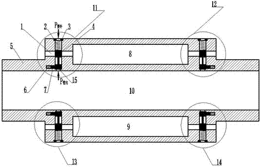
[0029] figure 1 It is a structural schematic diagram of the method for controlling the switch of the downhole detection device by the downhole tubing hydraulic trigger device of the present invention.

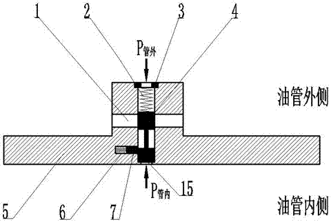
[0030] Depend on figure 1 It can be seen that the hydraulic trigger devices 11, 12, 13, 14 are integrated with the oil pipe 10 and the sealing chambers 8, 9 of the detection device; the control circuit channel 15 is set between the inner and outer walls of the oil pipe 10; and the working flow channel 1 is opened according to the application requirements; Put the piston 4 in the control channel, and add the compression spring A2 and the head 3 to one end of the piston 4. Before the hydraulic trigger device of the downhole tubing is triggered, the working channel 1 remains closed; for the hydraulic trigger device 11 of the downhole tubing, by adding oil Hydraulic pressure ...


PUM


Abstract

The invention relates to the technical field of oil exploitation, and provides a method for controlling on-off of an underground detecting device. An underground oil pipe hydraulic triggering device is used for controlling on-off of the underground detecting device, and the hydraulic triggering device can be integrated with an oil pipe and the detecting device. A control loop channel is arranged on the part, between the inner wall and the outer wall of the oil pipe, of the hydraulic triggering device, and a spring and a piston are arranged in the control loop channel to control the hydraulic triggering device. A working runner is formed according to application needs. Before the hydraulic triggering device is triggered, the original connecting and disconnecting states of the working runner are kept. The connecting and disconnecting states of the working runner are changed by increasing the hydraulic pressure in the oil pipe and triggering the hydraulic triggering device, and the on-off of the underground detecting device is controlled. After the hydraulic triggering device is triggered, it is ensured that the inner side and the outer side of the oil pipe are not communicated, and the oil pipe cannot release pressure to the sleeve space underground. By means of the method and device, the application limitation of cable transmission signals in a horizontal well and a large inclined well can be effectively overcome, and the clamping and blocking risks of horizontal well logging are eliminated.

Description

[0001] Technical field: [0002] The invention relates to the technical field of petroleum exploitation, in particular to the technical field of switch control of downhole equipment for petroleum exploitation. [0003] Background technique: [0004] In the existing vertical oil well logging, logging instruments and connecting cables can be lowered into the target well section by their own gravity. In the horizontal section of horizontal wells or the deep well section of highly deviated wells, logging instruments can no longer rely on gravity. Dragging the signal cable down to the target position means that there is a problem with the accessibility of logging tools for the horizontal section of a horizontal well or the deep well section of a highly deviated well. [0005] At present, the American Schlumberger company has specially developed the Flagsip (robot crawler). The Flagsip relies on the power provided by the cable to climb into the target position with instruments, signa...

Claims


Application Information

Patent Timeline
Patent Type & Authority Patents(China)
IPC IPC(8): E21B47/00
CPCE21B47/00
Inventor 梅坚
Owner MIANYANG GUMEI TECH
Why Eureka
Try Eureka