An electromagnetic induction linear displacement sensor

A technology of linear displacement and electromagnetic induction, applied in the direction of using electric/magnetic devices to transmit sensing components, using electromagnetic means, instruments, etc., can solve the problems of unfavorable wide application, etc., to increase the degree of induction signal, avoid mechanical errors, width and The effect of small thickness

Active Publication Date: 2019-10-15
CHONGQING UNIV OF TECH
View PDF5 Cites 1 Cited by
  • Summary
  • Abstract
  • Description
  • Claims
  • Application Information

AI Technical Summary

Problems solved by technology

[0004] In addition, in order to reduce the impact of the linear displacement sensor cable on its application, the application object often hopes that the sensor is a stator or a mover with a single lead. its wide application

Method used


Image

  • An electromagnetic induction linear displacement sensor
  • An electromagnetic induction linear displacement sensor
  • An electromagnetic induction linear displacement sensor

Examples


Embodiment 1

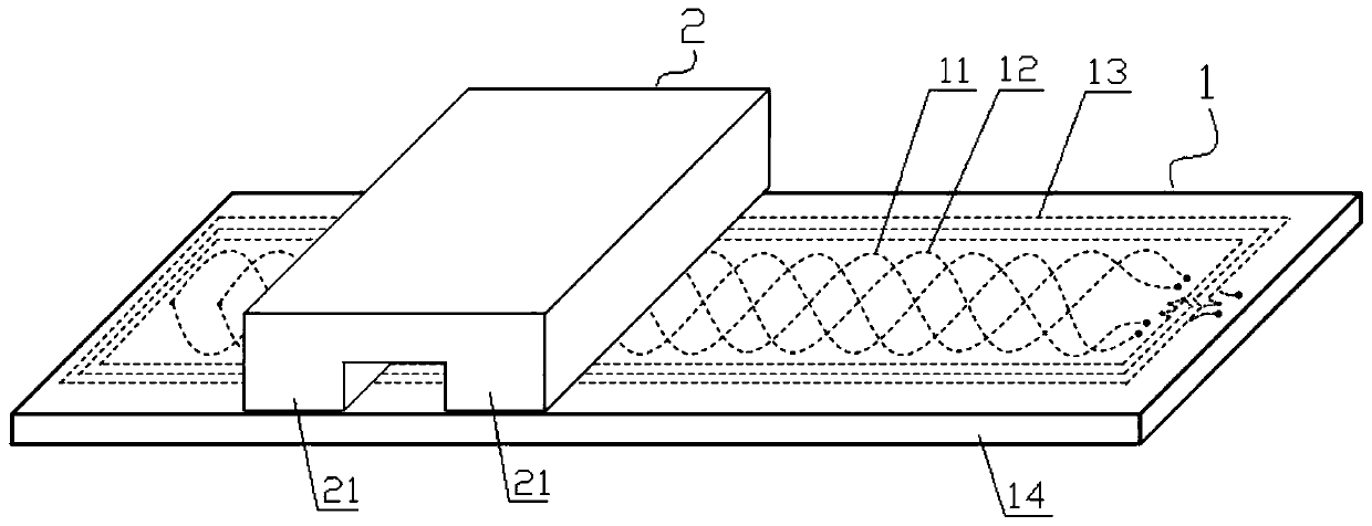
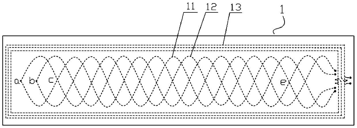
[0027] Embodiment 1: as figure 1 , figure 2 The electromagnetic induction type linear displacement sensor shown includes a fixed ruler 1 and a moving ruler 2 facing and parallel to the fixed ruler 1 with a gap of 0.1 mm to 1 mm.

[0028] The fixed length 1 is composed of a magnetically conductive fixed-length base 14 (that is, the fixed-length base 14 is made of a magnetically permeable material) and a sensing unit arranged on the surface of the fixed-length base 14. The sensing unit is equipped with a first coil linear array 11. The second coil array 12 and the printed circuit board of the planar rectangular spiral coil group. The first coil line array 11 and the second coil line array 12 all have the same starting position, the amplitude is 3mm (ie A=3mm), the period is 16mm (ie W=16mm), the number of periods is 4.5, and the initial phase The first sinusoidal coil and the second sinusoidal coil with angles of 0 and π are formed (that is, the winding curve of the first sin...

Embodiment 2

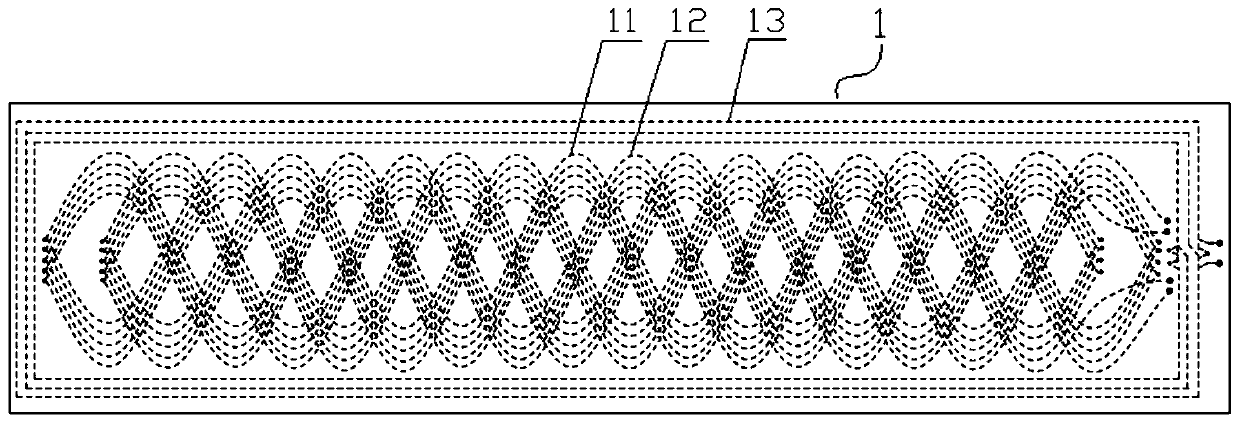
[0034] Embodiment 2: as image 3 As shown, the partial structure of the electromagnetic induction linear displacement sensor of this embodiment is the same as that of Embodiment 1, the difference is that: the first coil line array 11 and the second coil line array 12 are composed of five identical and mutually parallel coils The groups are connected in series through holes, and each coil group consists of the first sine coil and the second sine coil with the same starting position, 3mm amplitude, 16mm period, 4.5 periods, and initial phase angles of 0 and π. Coil composition (that is, the winding curve of the first sinusoidal coil is The winding curve of the second sinusoidal coil is The initial positions of the 5 coil groups of the first coil array 11 are aligned along the measurement direction, the distance between two adjacent coil groups perpendicular to the measurement direction is 0.6mm, and the 5 first sinusoidal coils of the first coil array 11 and 5 second sinusoi...

Embodiment 3

[0039] Embodiment 3: The partial structure of the electromagnetic induction linear displacement sensor of this embodiment is the same as that of Embodiment 1, except that the moving ruler 2 is a conductive metal and a non-magnetic material. The first coil line array 11 and the second coil line array 12 are as exciting coils, and the planar rectangular spiral coil group is as the induction coil, and the current amplitude of feeding in the first coil line array 11 is 1 m The excitation current i1 = I m sin (ωt), the current amplitude of passing through in the second coil line array 12 is I m The excitation current i 2 = I m cos(ωt), when the moving ruler 2 and the fixed ruler 1 move relative to each other in the measuring direction, the magnetic field coupling between the first coil array 11, the second coil array 12 and the planar rectangular spiral coil group will occur periodically change, the planar rectangular spiral coil group generates and outputs an induction signal e...


PUM


Abstract

The invention discloses an electromagnetic induction type linear displacement sensor, which comprises a fixed length and a moving ruler. The moving ruler is a metal body with rectangular teeth. The printed circuit board of the coil line array, the second coil line array and the plane rectangular spiral coil group, the first coil line array and the second coil line array are composed of the first and second sinusoidal coils, and the plane rectangular spiral coil group consists of four The same planar rectangular spiral coils are connected in series. The first and second coil arrays are fed with two-phase orthogonal alternating excitation signals or the planar rectangular spiral coil is fed with one-phase alternating excitation signals, and an alternating magnetic field will be generated on the surface of the fixed scale. When the moving scale moves relative to the fixed scale , the planar rectangular spiral coil or the first and second coil arrays will generate an induction signal that has a specific functional relationship with the displacement of the moving scale, and the corresponding displacement can be obtained after calculation. The invention is suitable for being integrated with application objects, can avoid installation errors and improve measurement accuracy.

Description

technical field [0001] The invention belongs to the technical field of precision measurement sensors, and in particular relates to an electromagnetic induction type linear displacement sensor. Background technique [0002] The linear motion unit on the machine tool often requires a linear displacement sensor to provide position feedback in order to achieve better linear positioning accuracy. Common linear displacement sensors include gratings, capacitors, and inductive synchros. However, in the harsh working environment with more oil, dust, vibration, etc., the application of some linear displacement sensors with higher environmental requirements, such as photoelectric type and capacitive type, has certain restrictions. Its strong environmental adaptability has been well applied. [0003] At the same time, the application objects of some linear displacement sensors often have certain restrictions on the volume of the sensor. It is hoped that the sensor will occupy as littl...

Claims


Application Information

Patent Timeline
Patent Type & Authority Patents(China)
IPC IPC(8): G01B7/02G01D5/20
Inventor 汤其富董良浩彭东林武亮陈锡侯徐是
Owner CHONGQING UNIV OF TECH
Why Eureka
Try Eureka