
A Computational Method for Gas Slip Flow in Microfluidic Devices with Complicated Geometric Boundaries

A technology of microfluidic devices and computing methods, which is applied in computing, instruments, and special data processing applications, etc., can solve the problems of less research, and achieve the effect of convenient use and strong adaptability to geometric boundaries

Inactive Publication Date: 2017-06-27
闫寒 +1
View PDF1 Cites 0 Cited by
  • Summary
  • Abstract
  • Description
  • Claims
  • Application Information

AI Technical Summary

Problems solved by technology

[0010] The velocity slip model is the key to modeling the slip flow region using the N-S equation. Researchers have proposed a variety of slip models to describe the slip of gas at the boundary, but these slip models are generally proposed for smooth planes. Slip models for surfaces with curvature and even rough surfaces are less well studied

Method used


Image

  • A Computational Method for Gas Slip Flow in Microfluidic Devices with Complicated Geometric Boundaries
  • A Computational Method for Gas Slip Flow in Microfluidic Devices with Complicated Geometric Boundaries
  • A Computational Method for Gas Slip Flow in Microfluidic Devices with Complicated Geometric Boundaries

Examples


example 1

[0042] Example 1: Using the proposed calculation method, the pressure-driven slip flow in a circular microchannel is calculated. The geometric boundary of the circular microchannel is not a plane but an arc surface, and due to the regular geometric shape, an analytical solution exists. Therefore, the correctness of this method can be verified through this example. The flow characteristics in the microchannel can be expressed by the Poiseuille number (Po):

[0043]

[0044] In the formula, F is the friction factor, Re is the Reynolds number, is the average pressure gradient in the flow direction, D h is the hydraulic diameter, is the average velocity at the cross section. For the macroscopic circular pipe flow, without considering the rarefaction effect, Po=64. For circular microchannels, Po and Kn numbers satisfy the following relationship:

[0045]

[0046] Take (2-σ t ) / σ t =1.6, under different Kn numbers, the analytical and numerical solutions obtained are ...

example 2

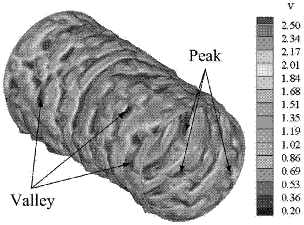
[0050] Example 2: Calculation of the effect of random surface roughness on slip flow in a circular microchannel. The geometric boundaries of random rough circular microchannels are complex, and the conventional sliding boundary conditions are difficult to deal with, but using this method, better results can be obtained. figure 1 Given the slip velocity at the surface of the random rough microchannel, it can be found that the slip velocity is small at the position with relatively large roughness (trough); while at the position with relatively small roughness (peak), the slip velocity Great speed. Similar results were obtained when researchers used different methods to study the effect of roughness profiles on 2D slip flow. However, this method can accurately capture the gas slip characteristics of the three-dimensional random rough surface.


PUM


Abstract

The invention relates to the field of fluid mechanics, in particular to a computation method for gas gliding flow in a micro-fluid device in a complex geometrical boundary. The method includes the steps that firstly, based on a finite volume method, a computational domain and a computational boundary are discretized through mesh generation software; secondly, based on a Maxwell molecular model and mass, momentum and energy conservation in a Knudsen layer, a speed gliding model suitable for a complex geometrical surface is acquired; thirdly, by the application of the model and in combination with fluid computation business software ANSYS and FLUENT, a user-defined function is compiled, and the gliding speed of rare gas on the complex geometrical surface is computed. The geometrical boundary is high in adaptability, and the method is capable of being combined with the existing business software and convenient to use.

Description

[technical field] [0001] The invention relates to the technical field of fluid mechanics, in particular to a calculation method for gas slip flow in a microfluidic device under complex geometric boundaries. [Background technique] [0002] In recent decades, MEMS (Micro-Electro-Mechanical Systems) technology has achieved rapid development. MEMS products have spread across many fields such as aerospace, medical treatment, and automobile manufacturing, and have had a huge impact on people's lives. Among them, microfluidic devices are an important part of MEMS devices, and are widely used in fields such as extraction of biology, aerospace, environmental monitoring, and chemistry. For example, microchannels can separate cells and cool integrated circuits, and micro-spray heads are widely used in inkjet Printer, micro-contraction-expansion nozzle for micro-propulsion systems of small satellites. Therefore, the study of microfluidics has gradually become an important branch of MEM...

Claims


Application Information

Patent Timeline
Patent Type & Authority Patents(China)
IPC IPC(8): G06F17/50
Inventor 闫寒张文明
Owner 闫寒
Learn More