Stranding Machine Pitch Control Mechanism

A technology of control mechanism and stranding machine, which is applied in the auxiliary device of rope making, cable/conductor manufacturing, textile and paper making, etc., which can solve the problem of not being able to meet the needs of rapid and diversified markets, increase production costs, and replace processes. Complicated problems, to achieve the effect of shortening the production cycle, easy to implement, and flexible collocation

Inactive Publication Date: 2017-07-21
DONGGUAN NEW ENSHIANG MACHINERY ENTERPRISE
View PDF4 Cites 0 Cited by
  • Summary
  • Abstract
  • Description
  • Claims
  • Application Information

AI Technical Summary

Problems solved by technology

[0003] When the twisting machine in the prior art needs to change the twist pitch, it is necessary to manually replace the corresponding twist pitch gear set. The replacement process is cumbersome, the operation is complicated, and many people are required to cooperate, which is time-consuming and laborious, which increases the production cost, and the efficiency is low, which affects the production. Efficiency, unable to meet the needs of the current rapid and diverse market
[0004] There is also a servo motor added to the pulley on the market, and then the speed of the pulley is controlled by the controller to change the size of the lay pitch accordingly, that is, the twist pitch is changed by changing the speed of the lower pulley and the upper pulley, but Its cost is high and it is difficult to realize

Method used


Image

  • Stranding Machine Pitch Control Mechanism
  • Stranding Machine Pitch Control Mechanism
  • Stranding Machine Pitch Control Mechanism

Examples


Embodiment Construction

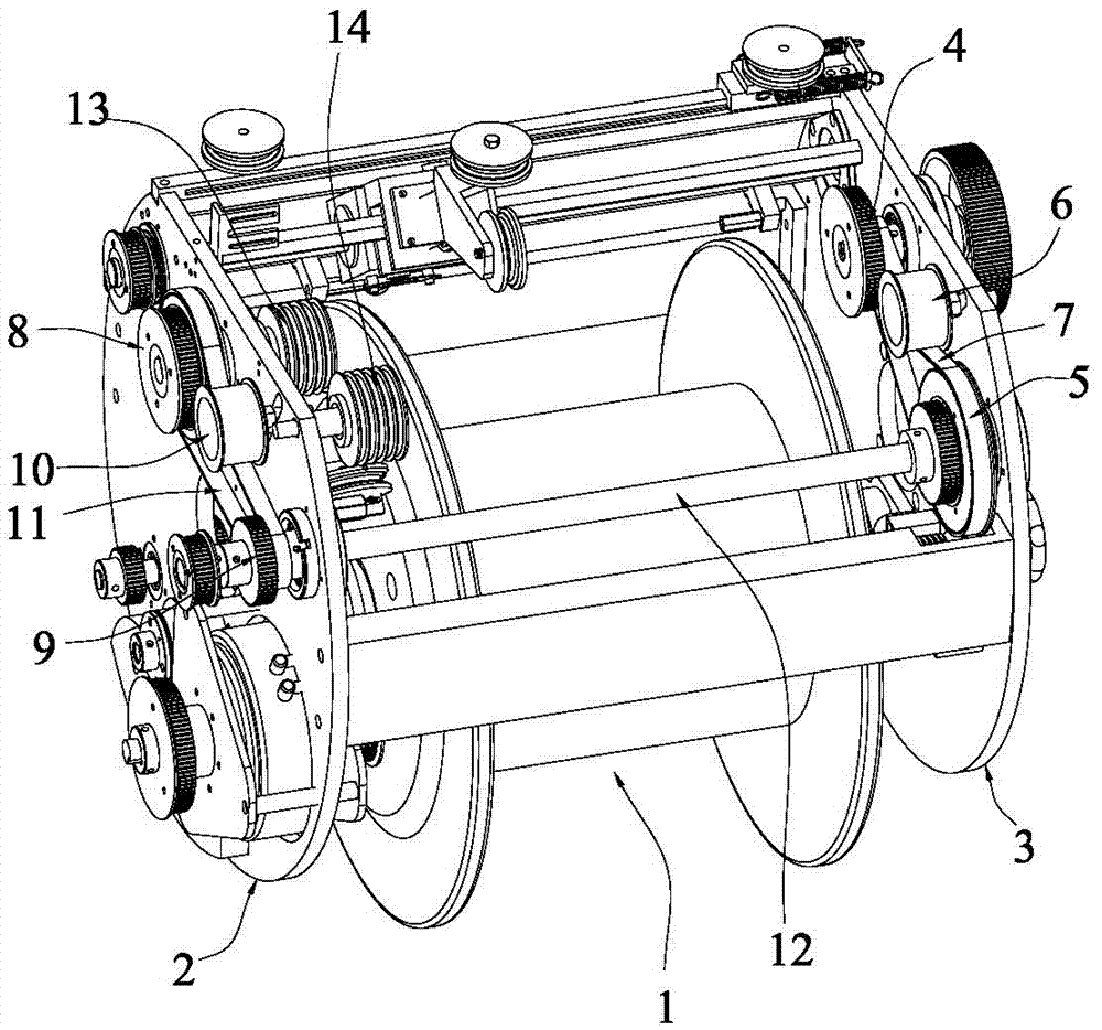
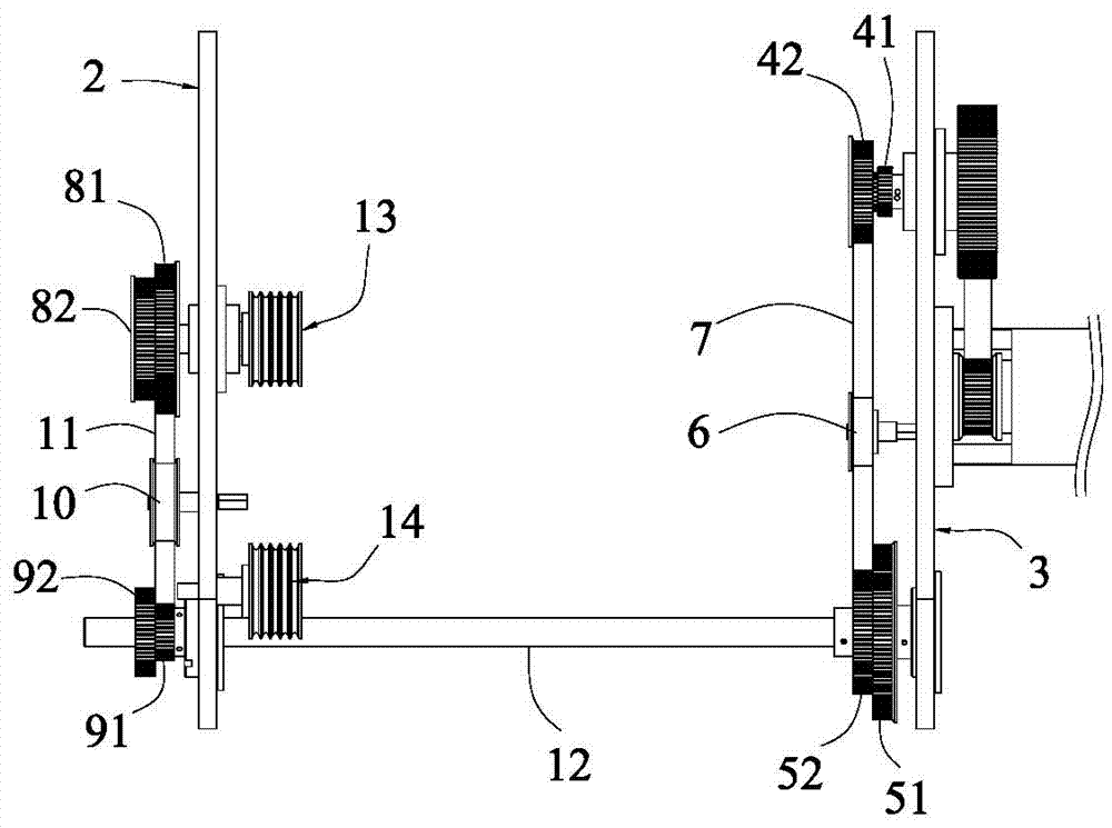
[0019] see figure 1 and figure 2 , a stranding machine pitch control mechanism provided in this embodiment, which includes a bobbin 1 and a left disk 2 and a right disk 3 arranged on both sides of the bobbin 1, and the right disk 3 is provided with a group A pulley 4. The pulley 5 of group B and the right pressure pulley 6, the pulley 4 of group A is connected with the pulley 5 of group B through the right belt 7, the right pressure pulley 6 is located between the pulley 4 of group A and the pulley 5 of group B, and the top pressure On the right belt 7; the left disc 2 is provided with a C group pulley 8, a D group pulley 9 and a left pressure pulley 10, and the D group pulley 9 communicates with the B group pulley 5 through a transmission shaft 12 Connection, the D group pulley 9 is connected with the C group pulley 8 through the left belt 11, the left pressure pulley 10 is located between the C group pulley 8 and the D group pulley 9, and presses on the left belt 11. The ...


PUM

PropertyMeasurementUnit
diameteraaaaaaaaaa

Abstract

The invention discloses a pitch control mechanism of a stranding machine. The pitch control mechanism comprises a bobbin, a left disc and a right disc. A right pinch roller, an A group of belt pulley and a B group of belt pulley are arranged on the right disc; a left pinch roller, a C group of belt pulley and a D group of belt pulley are arranged on the left disc. The pitch control mechanism has the advantages that the pitch control mechanism is ingenious and reasonable in design, and belt-pulley transmission is substituted for conventional gear transmission, so that structure is simplified effectively, and simplicity and convenience in operation are achieved; when stranding pitch adjustment is needed, the belt pulleys, with the corresponding tooth numbers, in the A, B, C and D groups of belt pulleys are selected according to stranding pitches as needed, and then left and right belts are tensioned by the left pinch roller and the right pinch roller to complete adjustment, so that adjustment speed is high, flexible matching is achieved, stranding pitch adjustment range is wide, time and labor are saved, a large amount of time and manpower are saved effectively, working efficiency is high, the whole production cycle is shortened, stranding quality is improved, and production cost is reduced; in addition, the pitch control mechanism is simple and compact in overall structure, easy to produce, low in cost, high in working stability and beneficial to wide popularization and application, and has few used parts.

Description

technical field [0001] The invention relates to the technical field of stranding machine pitch adjustment, in particular to a stranding machine pitch control mechanism. Background technique [0002] Stranding machine is a kind of wire that can be widely used in various soft / hard conductor wires (copper wire, enameled wire, tinned wire, copper-clad steel and copper-clad aluminum, etc.) and electronic wires (power cord, earphone wire, telephone wire, PVC Cables and network cables, etc.) twisting mechanical equipment, so that many single conductors are twisted into one strand to meet the technical requirements of the wire. [0003] When the twisting machine in the prior art needs to change the twist pitch, it is necessary to manually replace the corresponding twist pitch gear set. The replacement process is cumbersome, the operation is complicated, and many people are required to cooperate, which is time-consuming and laborious, which increases the production cost, and the effi...

Claims


Application Information

Patent Timeline
Patent Type & Authority Patents(China)
IPC IPC(8): H01B13/02
CPCD07B7/022D07B2207/409
Inventor 徐明煃
Owner DONGGUAN NEW ENSHIANG MACHINERY ENTERPRISE
Why Eureka
Try Eureka