Straight-line multipath fuse box

An in-line fuse box technology, applied in circuits, emergency protection devices, electrical components, etc., can solve the problems of large size, limited number of fuses connected to PCB board type fuse boxes, inconvenient installation and maintenance, etc., to achieve small size, Ease of diagnosis and maintenance, and improved safety

Active Publication Date: 2015-02-25
XINXIANG GUANGMING ELECTRIC APPLIANCE CO LTD
View PDF4 Cites 9 Cited by
  • Summary
  • Abstract
  • Description
  • Claims
  • Application Information

AI Technical Summary

Problems solved by technology

[0004] The present invention aims to solve the technical problems of the existing PCB board-type fuse box with limited number of access fuses, inconvenient installation and maintenance, and large volume

Method used


Image

  • Straight-line multipath fuse box
  • Straight-line multipath fuse box
  • Straight-line multipath fuse box

Examples


Embodiment 1

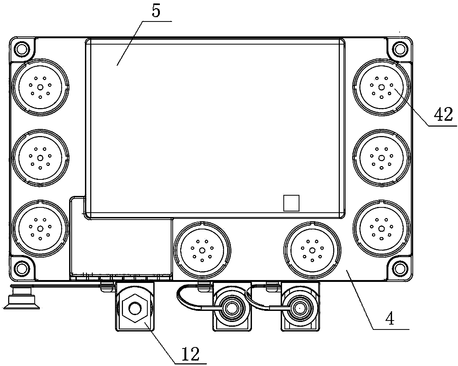
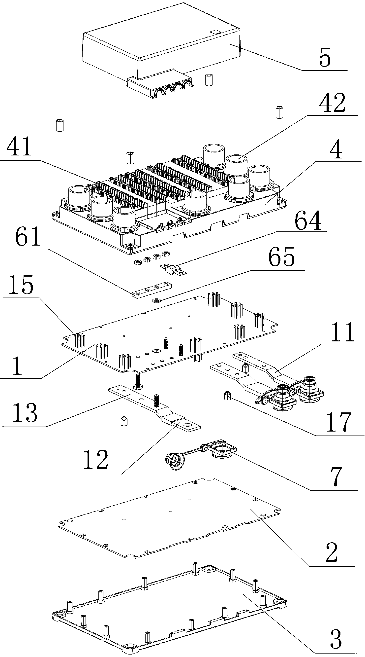
[0035] Embodiment 1: An in-line multi-way fuse box, including a box body and a PCB circuit board installed in the box body, the PCB circuit board includes an upper board 1 and a lower board 2, and three fuses are arranged on the back of the upper board 1 Parallel input copper bars, input copper bars 11 include power supply terminals 12 extending beyond the edge of the upper board, and circuit connection sections 13 fastened to the back of the upper board by conductive bolts, on the front of the upper board 1, the input copper bars A row of insurance slots 14 are respectively provided on both sides of the circuit connection section 13 of the circuit, and the vertical distance from each insurance slot to the input copper bar 11 is equal. The circuit connecting section 13 of the copper bar 11 is electrically connected; the front of the upper board 1 is also provided with a wiring harness access terminal 15; the lower board 2 is installed on the back of the upper board 1, and betwe...

Embodiment 2

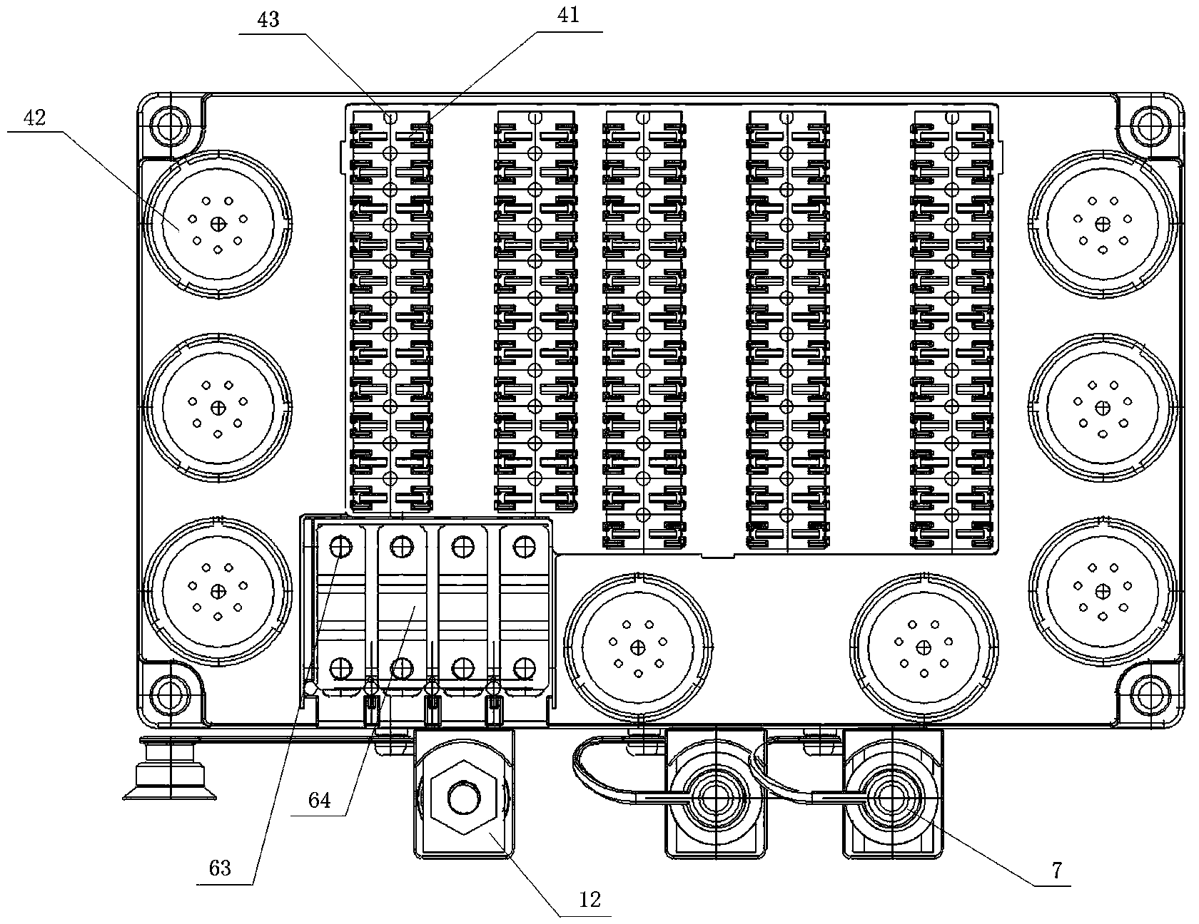
[0039] Embodiment 2: a kind of in-line multi-way fuse box, such as Figure 1 to Figure 5 As shown, the difference from Embodiment 1 is that it also includes a group of high-current safety devices. The high-current safety device includes a dedicated copper bar 61, fastening bolts 62, and 4 safety lead-out bolts. The special copper bar 61 It is arranged on the front of the upper board 1 and forms a cross intersection with one of the input copper bars. A bolt access hole is opened at the cross position of the upper board 1, and a cylindrical copper ring 65 is arranged in the bolt access hole. The copper ring The thickness of 65 is greater than the thickness of the upper plate 1, and the fastening bolts 62 pass through the lower input copper bar 11, the middle copper ring 65 and the upper dedicated copper bar 61 in order to fasten them together to form an electrical connection; Bolts 63 pass through the upper plate 1 and the dedicated copper bar 61 to form a bolt-fixed insurance a...

Embodiment 3

[0040] Embodiment 3: An in-line multi-way fuse box, which differs from Embodiment 2 in that there are four input copper bars and 90 fuse slots.


PUM


Abstract

The invention discloses a straight-line multipath fuse box. The technical problems that the number of fuses connected into an exiting PCB type fuse box is limited, mounting and maintenance are inconvenient, and the size is large are solved. The straight-line multipath fuse box comprises a box body and a PCB arranged in the box body, the PCB comprises an upper board body and a lower board body, at least one input copper row is arranged on the back face of the upper board body, the positions, on the two sides of a circuit connecting segment of each input copper row, of the front face of the upper board body are each provided with a row of fuse slots, and the vertical distances between the fuse slots and the input copper rows are equal. Wiring harness access ends are arranged on the front face of the upper board body. The box body comprises a bottom board and a panel which are buckled. Fuse inserting openings are formed in the positions, corresponding to the fuse slots, of the panel, and wiring harness ports are arranged at the positions, corresponding to the wiring harness access ends, of the panel. The straight-line multipath fuse box has the advantages that the number of integrated fuse paths is large, the performance of the fuse box is excellent, the size is small, and wiring, mounting and fault maintenance are very convenient.

Description

technical field [0001] The invention relates to the technical field of electrical equipment, in particular to an in-line multi-way fuse box. Background technique [0002] As a kind of electrical equipment, fuse electrical box is usually used in automatic mechanical equipment such as motor vehicles and ships. From the structural form of the fuse box, it can be mainly divided into plug-in fuse box, bus bar fuse box, wiring fuse box, printed circuit board fuse box and electronic integrated fuse box. Among them, the more commonly used printed circuit board fuse box is the PCB board type fuse box. Most of the circuit boards used are double-sided copper-clad circuit boards, and the rear outlet method, that is, the connectors are arranged on the back of the box. However, as the functions of electrical equipment increase, the number of wiring harnesses connected to the fuse box will inevitably increase. Using the rear outlet method will cause the overall volume of the fuse box to b...

Claims


Application Information

Patent Timeline
Patent Type & Authority Applications(China)
IPC IPC(8): H01H85/20
CPCH01H85/2015
Inventor 胡广举
Owner XINXIANG GUANGMING ELECTRIC APPLIANCE CO LTD
Why Eureka
Try Eureka