Novel energy-efficient fin type electric heating pipe

An electric heating tube, high-efficiency and energy-saving technology, applied in the direction of the heating element shape, etc., can solve the problems of short service life of the electric heating tube, unsatisfactory heat dissipation effect, loose solder joints, etc., to achieve enhanced heat dissipation efficiency, good heat dissipation effect, and convenient The effect of welding process

Active Publication Date: 2015-02-25
江苏大唐电器制造有限公司
View PDF5 Cites 3 Cited by
  • Summary
  • Abstract
  • Description
  • Claims
  • Application Information

AI Technical Summary

Problems solved by technology

The above-mentioned electric heating tube mainly adopts linear heat dissipation fins. When the heat dissipation fins are wound on the circular electric heating tube shell, the limitation on the width of the fins is further increased, and the heat dissipation effect is not ideal.
On the other hand, the internal stress of the heat dissipation fins after spiral winding is relatively large, and it is difficult to weld, and the solder joints are prone to loosening after a period of use, resulting in a short service life of the entire electric heating tube

Method used


Image

  • Novel energy-efficient fin type electric heating pipe
  • Novel energy-efficient fin type electric heating pipe
  • Novel energy-efficient fin type electric heating pipe

Examples


Embodiment Construction

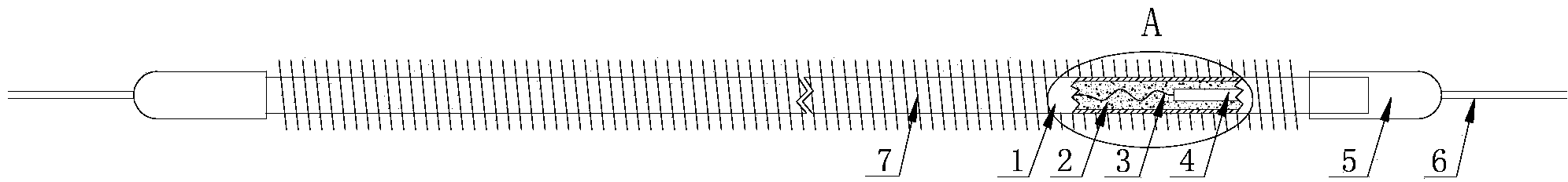
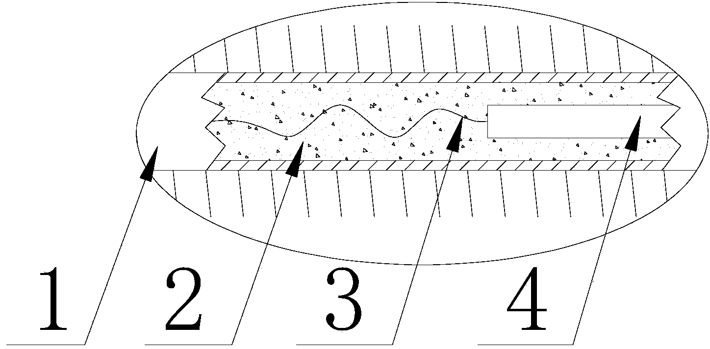
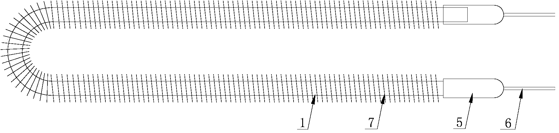
[0021] like Figure 1 to Figure 3 As shown, the new high-efficiency and energy-saving finned electric heating tube includes a shell 1, a heating wire 3 arranged in the shell 1, and a thermally conductive insulating filler 2 filled between the shell 1 and the heating wire 3. The shell 1 Mounting seats 5 are respectively provided at both ends, and terminal electrodes 4 are provided on the mounting seats 5. Strip-shaped cooling fins 7 are spirally wound on the outer surface of the housing 1. The cooling fins 7 are provided with continuously distributed A fan-shaped concave-convex structure (not shown in the figure), the constricted end of the fan-shaped concave-convex structure is close to the surface of the housing 1 , and the expanded end is close to the outer edge of the heat dissipation fin 7 .

[0022] In this embodiment, the distance between the expanded end of the fan-shaped concave-convex structure and the outer edge of the heat dissipation fin 7 is less than or equal to ...


PUM


Abstract

The invention relates to a novel energy-efficient fin type electric heating pipe which comprises a shell, a heating wire and heat-conducting insulating padding. A strip-shaped cooling fin is spirally wound on the outer surface of the shell and provided with continuously-distributed fan-shaped concave-convex structures, the shrinkage end of each structure is close to the surface of the shell, the unfolded end of each structure is close to the outer edge of the fin, and a smooth arc transition face is arranged between each unfolded end and the outer edge of the cooling fin. Mounting seats are connected with the shell in a sealed mode, power lines are arranged on the end portions of the mounting seats, and the power lines are connected with the heating wire in the shell through the mounting seats. The continuous concave-convex structures which are arranged at intervals are adopted by the cooling fin, the fin can be conveniently wound on the shell, and internal stress of the cooling fin is effectively eliminated. Welding machining is facilitated, the width of the fin is not limited, the cooling area is enlarged, the cooling effect is better, and the service life of the electric heating pipe is longer. Cooling efficiency of the fin is enhanced, the power of the electric heating pipe can be properly lowered, and the purposes of efficiency raising and energy saving are achieved.

Description

technical field [0001] The invention relates to an electric heating device, in particular to a novel high-efficiency and energy-saving finned electric heating tube mainly used for heating gas. Background technique [0002] The electric heating tube used for heating gas generally includes a shell and an electric heating wire arranged in the shell. The space between the electric heating wire and the shell is filled with heat-conducting insulating medium such as magnesia, and the two ends of the electric heating tube shell are respectively provided with mounting seats. , There is a power cord connected to the heating wire on the mounting base. Existing finned electric heating tubes usually wrap a circle of stainless steel strips on the outer surface of the shell to form erected fins to increase the heat dissipation area of ​​the electric heating tube to improve the thermal efficiency of the electric heating tube during operation. At present, due to the limitation of the windin...

Claims


Application Information

Patent Timeline
Patent Type & Authority Applications(China)
IPC IPC(8): H05B3/50
Inventor 唐伟
Owner 江苏大唐电器制造有限公司
Why Eureka
Try Eureka