Iron filings box of lathe

A technology of iron filings and lathes, applied in turning equipment, maintenance and safety accessories, auxiliary devices, etc., can solve problems such as inconvenient cleaning, potential safety hazards, small volume of iron filings tray, etc., to eliminate potential safety hazards and facilitate centralized cleaning and operation convenient effect

Inactive Publication Date: 2015-03-04
CHONGQING YAOYONG SHOCK ABSORBER
View PDF8 Cites 4 Cited by
  • Summary
  • Abstract
  • Description
  • Claims
  • Application Information

AI Technical Summary

Problems solved by technology

[0002] In general lathes, only a chip tray is designed at the lower end of the bed for loading the chips after turning. Processing of tubular workpieces (such as motorcycle shock absorber front fork tubes) produces more iron filings, which need to be removed more than 2 times in the shift; The end of the inner hole flows out, and the iron filings are scattered on the ground, which is irregular and inconvenient to clean, posing a safety hazard

Method used


Image

  • Iron filings box of lathe
  • Iron filings box of lathe
  • Iron filings box of lathe

Examples


Embodiment Construction

[0036] The implementation of the present invention will be illustrated by specific specific examples below, and those skilled in the art can easily understand other advantages and effects of the present invention from the contents disclosed in this specification.

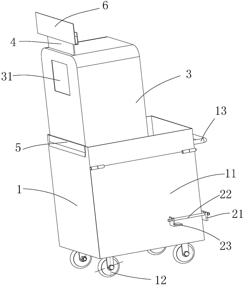
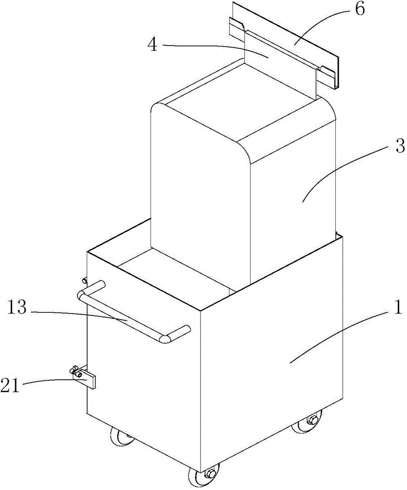
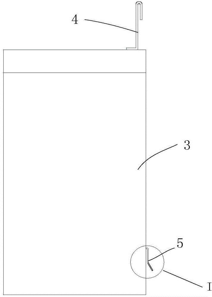
[0037] Such as Figure 1 to Figure 4 As shown, the present invention provides a lathe chip box, which includes a box body 1 with an open upper end, and a running wheel 12 is arranged under the box body 1, the front wheel is a fixed wheel, and the rear wheel is a rotating wheel, which is convenient for pushing and pulling the chip box. A handle 13 is provided at the rear of the box body 1, and a chip removal door 11 is provided on the side of the box body 1. A chip cover 3 is detachably installed on the top. A chip inlet 31 is provided on the top of the chip cover 3 . The lower part of the chip cover 3 extends into the upper part of the box body 1 .

[0038] A block 23 is arranged on the chip removal door 11, and a ...


PUM


Abstract

The invention provides an iron filings box of a lathe. The iron filings box comprises a box body with an upper opening. Traveling wheels are arranged under the box body. A handle is arranged at the rear of the box body. An iron filings discharge door is arranged on the side of the box body and hinged to the same and clamped by a clamping part on the box body. An iron filings hook is detachably arranged on the box body. An iron filings inlet is formed in the upper portion of the iron filings hook. The lower portion of the iron filings hook extends into the box body. An iron filings outlet is formed in the lower end of the iron filing hook. The iron filings box has the advantages that the iron filings are conveniently received from the head and the tail of the lathe and directly fall into the box body through the iron filings hook; with the iron filings discharge door, the iron filings are conveniently removed from the box body at any moment; by the aid of a hook and a clamping plate, the iron filings hook is conveniently mounted on and dismounted from the lathe and the box body; operation is convenient; the iron filings are prevented from scattering to cause unnecessary troubles and are removed concentratedly; removing time is shortened, the filings site is clean and tidy, and potential safety hazard is eliminated.

Description

technical field [0001] The invention relates to the technical field of mechanical processing, in particular to a lathe chip box. Background technique [0002] In general lathes, only a chip tray is designed at the lower end of the bed for loading the chips after turning. Processing of tubular workpieces (such as motorcycle shock absorber front fork tubes) produces more iron filings, which need to be removed more than 2 times in the shift; The end of the inner hole flows out, and the iron filings are scattered on the ground, which is irregular and inconvenient to clean, posing a safety hazard. Contents of the invention [0003] In view of the above-mentioned deficiencies in the prior art, the purpose of the present invention is to provide a lathe chip box, which can hold the chip at the head and tail of the lathe, prevent the chip from scattering on the ground, prevent the chip from hurting people, and is easy to operate. [0004] In order to achieve the above purpose and...

Claims


Application Information

Patent Timeline
Patent Type & Authority Applications(China)
IPC IPC(8): B23B25/00B23Q11/00
CPCB23B25/00B23Q11/0042
Inventor 张杰李耀勇谭庆洪田祥云黄强翁长江周明元杨志明
Owner CHONGQING YAOYONG SHOCK ABSORBER
Why Eureka
Try Eureka