
Welding process method for aluminum structure roof of EMU driver's cab

A technology of aluminum structure roof and process method, which is applied in the direction of vehicle parts, manufacturing tools, welding equipment, etc., and can solve the problems of large fluctuations in the quality of products produced by the aluminum structure of the driver's cab, large free deformation of the top position of the driver's cab, and problems in the driver's cab assembly. Long manufacturing cycle and other issues, to achieve the effect of ensuring the length, width, height and arc size of the car roof, reducing the development and production cycle, shortening the synthesis time and workload

Active Publication Date: 2016-06-01
CRRC CHANGCHUN RAILWAY VEHICLES CO LTD
View PDF7 Cites 0 Cited by
  • Summary
  • Abstract
  • Description
  • Claims
  • Application Information

AI Technical Summary

Problems solved by technology

In the original plan, because a large number of parts were not combined into a whole separately, the welding position of the parts was difficult and the welding workload was large during the assembly of the parts, which resulted in a long manufacturing cycle of the driver's cab assembly, and the free deformation of the top position of the driver's cab was extremely large, resulting in The quality of aluminum structure production products fluctuates greatly

Method used


Image

  • Welding process method for aluminum structure roof of EMU driver's cab
  • Welding process method for aluminum structure roof of EMU driver's cab
  • Welding process method for aluminum structure roof of EMU driver's cab

Examples


Embodiment Construction

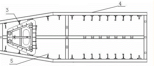
[0024] refer to figure 1 , figure 2 The assembly welding tooling involved in the present invention includes a reinforcing beam positioning structure 1, a roof curved beam positioning structure 2, a roof front window frame positioning structure 3, a clamp main frame 4, a roof longitudinal beam positioning structure 5, a reinforcing beam positioning structure, The roof curved beam positioning structure, the roof front window frame positioning structure, and the roof longitudinal beam positioning structure are respectively fixed on the fixture main frame.

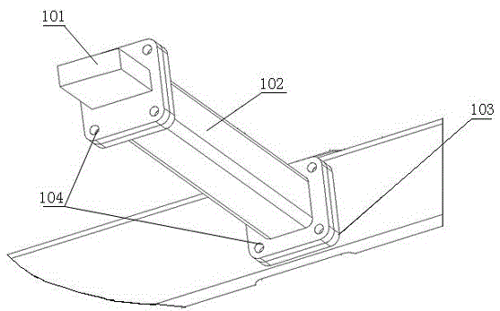
[0025] refer to image 3 , the reinforcing beam positioning structure includes a conformal positioning block 101, a connection support column 102, and a positioning mounting seat 103, the connection support column 102 is fixed on the positioning mounting seat 103 with bolts, and the conformal positioning block 101 is fixed on the connection support column 102 with bolts , 104 is a bolt connection hole, and the positioning m...


PUM


Abstract

The invention relates to an assembly welding process method for an aluminum structure ceiling of a driver cab of a motor train unit. The assembly welding process method is characterized in that (1) at the premise of not changing the integral structure of the original structure, ceiling modules are separated, the structure of the original driver cab is re-divided, one part of structure is separated from a left side wall structure and a right side wall structure, and is used as a longitudinal edge beam of the ceiling structure, and then bulk parts which cannot be singly combined in the original structure can form the ceiling welding structure; (2) a welding tooling adopting the reverse assembly and outer positioning method is used for positioning and clamping, the welding sequence of the new ceiling structure is adjusted, the welding of a ceiling window frame structure is firstly completed, then the welding of a ceiling skeleton and a front window frame is completed, and finally the welding of a ceiling skin and the skeleton is completed, so a five-shaft processing center can complete processing at one time. The assembly welding process method has the advantages that the existing production technique of the aluminum structure ceiling of the driver cab of the motor train unit is a full new technique, the product quality of the ceiling part is improved, the assembly welding difficulty of the aluminum structure ceiling of the driver cab is decreased, the production cycle and labor intensity of the driver cab assembly are improved, the production modularizing of the driver cab is improved, and the quality is conveniently guaranteed.

Description

technical field [0001] The invention relates to an assembly and welding process for rail passenger cars, in particular to an assembly and welding process for the streamlined driver's cab aluminum structure roof of an EMU. Background technique [0002] At present, there is no separate synthetic roof structure technology for the aluminum structure of the EMU driver's cab in China, and it is the first case of roof synthesis with a three-dimensional streamlined appearance. In the welding process of the original high-speed vehicle cab assembly, only the left and right side walls, the rear ring frame and the front window frame were separately synthesized. In the cab assembly process, these four parts were welded with the rest of the cab to complete the entire cab. . In the original plan, because a large number of parts were not combined into a whole separately, the welding position of the parts was difficult and the welding workload was large during the assembly of the parts, whi...

Claims


Application Information

Patent Timeline
Patent Type & Authority Patents(China)
IPC IPC(8): B23K31/02B23K37/04
CPCB23K31/02B23K37/04B23K2101/006
Inventor 邵有发陆培德夏常青
Owner CRRC CHANGCHUN RAILWAY VEHICLES CO LTD
Learn More