Aero-engine multistage rotor and stator unit body positioning and hoisting device

An aero-engine and rotor-stator technology, which is used in transportation and packaging, workpiece clamping devices, load-hanging components, etc., can solve the problems of affecting the balance effect of the rotor and the probability of collision and wear, and achieves easy promotion, radial axis The effect of firm orientation and wide application range

Inactive Publication Date: 2015-03-04
SHENYANG LIMING AERO-ENGINE GROUP CORPORATION
View PDF7 Cites 15 Cited by
  • Summary
  • Abstract
  • Description
  • Claims
  • Application Information

AI Technical Summary

Problems solved by technology

However, after the balance of the rotor assembly of the compressor meets the requirements, the rotor assembly may be reassembled after the rotor assembly is divided into lower blades and the stator is installed during transmission transfer, which affects the balance effect of the rotor.
For the unit body of the open case structure, after assembly, because the rotor stator is not in the state of the unit body, the probability of friction is relatively high; it is also necessary to study the use of new positioning and hoisting devices to meet the positioning and hoisting of aero-engines after assembly Require

Method used


Image

  • Aero-engine multistage rotor and stator unit body positioning and hoisting device
  • Aero-engine multistage rotor and stator unit body positioning and hoisting device
  • Aero-engine multistage rotor and stator unit body positioning and hoisting device

Examples


Embodiment Construction

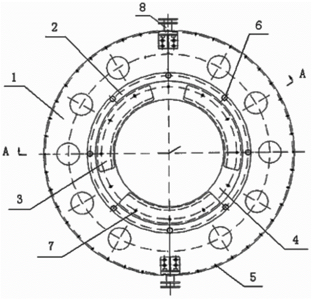
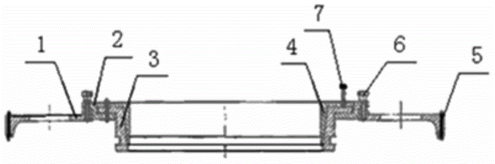
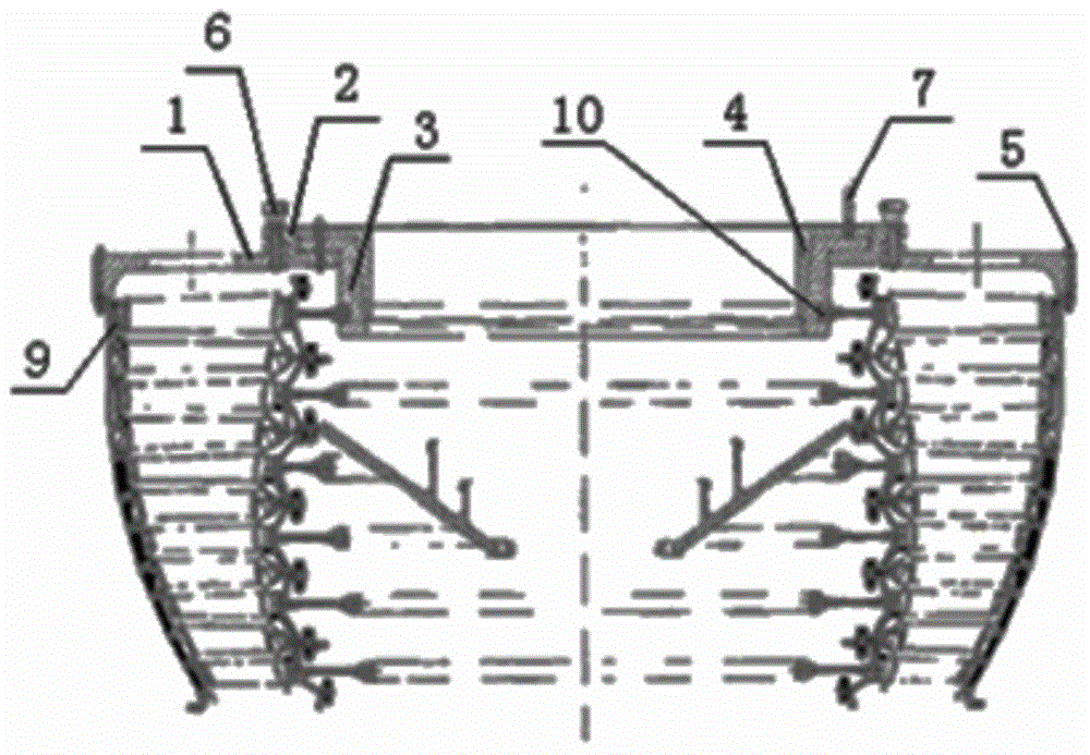
[0017] Such as figure 1 , 2 , 3, a device for positioning and hoisting the multi-stage rotor-stator unit of an aero-engine, including a process case 1, a trunnion 8, a bolt one 5, an adapter plate 2, a bolt two 6, a fixed plate 3, and an expansion core Ring 4 and bolt three 7, the process casing 1 is connected with the stator casing rear mounting edge 9 of the rotary stator unit body through bolt one 5; two trunnions 8 are arranged on the process casing 1; the rotary The adapter plate 2 is arranged inside the process casing 1, and the transfer plate 2 is connected to the process casing 1 by bolts 2 6; the fixed plate 3 is arranged inside the adapter plate, and the fixed plate It consists of three segments, the inner edge of the segment is a slope, and the outer edge of the segment is provided with a U-shaped groove, and the U-shaped groove is matched with the spoke plate 10 of the six-stage turbine disk of the rotor-stator unit body The expansion core ring 4 is arranged insi...


PUM


Abstract

The invention relates to an aero-engine multistage rotor and stator unit body positioning and hoisting device, which comprises a process cartridge receiver, a lug shaft, a first screw bolt, a transfer disc, a second screw bolt, a fixing plate, a core expansion ring and a third screw bolt, wherein the process cartridge receiver is connected with the back installing edge of a stator cartridge receiver of a rotor and stator unit body through the first screw bolt, the transfer disc is connected with the process cartridge receiver through the second screw bolt, the fixing plate consists of a plurality of fan-shaped sections, the inner edge of each fan-shaped section is a slope surface, the outer edge of each fan-shaped is provided with a U-shaped groove, the U-shaped groove is matched with a radial plate of the last-stage disc of the rotor and stator unit body, the core expansion ring is provided with a convex edge, the outer part of the convex edge is a circular conical surface, the circular conical surface is matched with the slope surface of the inner edge of the fixing plate, and the transfer disc, the fixing plate and the core expansion ring are connected through the third screw bolt. The device provided by the invention has the advantages that the positioning and the hoisting of the multistage rotor and stator unit body are realized, and the axial and radial collision of a rotor and a stator is avoided.

Description

technical field [0001] The invention relates to a device for locating and hoisting components, in particular to a device for locating and hoisting a multi-stage rotor-stator sub-unit body of an aero-engine. Background technique [0002] For many years, the turbine rotor-stator assembly of an aero-engine is to assemble the guide casing separately first and then assemble the turbine rotor, without forming a unit form, and the hoisting and assembly of the turbine guide casing and the turbine rotor are relatively simple. [0003] With the further improvement of the thrust-to-weight ratio and reliability of aero-engines, the design structure of the turbine-rotor-stator subunit is increasingly widely used in modern aero-engines. The special structural form of the turbine rotor-stator unit also puts forward higher requirements for the assembly and disassembly of the turbine. This structure requires the turbine rotor-stator to be assembled at the same time, and the relative position...

Claims


Application Information

Patent Timeline
IPC IPC(8): B25B11/00
CPCB66C1/54
Inventor 陈大丽巩孟祥贾朝波李倩华高福达
Owner SHENYANG LIMING AERO-ENGINE GROUP CORPORATION
Why Eureka
Try Eureka