Eureka AIR delivers breakthrough ideas for toughest innovation challenges, trusted by R&D personnel around the world.

OLED mask assembly preparation method

A mask assembly and mask technology, applied in the direction of ion implantation plating, metal material coating process, coating, etc., can solve the problems of poor straightness of the opening edge of small openings, affecting the edge quality of organic deposition layers, etc.

Inactive Publication Date: 2015-03-04
KUN SHAN POWER STENCIL
View PDF6 Cites 2 Cited by
  • Summary
  • Abstract
  • Description
  • Claims
  • Application Information

AI Technical Summary

Problems solved by technology

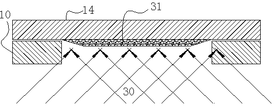
However, when this method is actually used to prepare a mask, due to the fact that the thickness of the plate used to make the mask is not absolutely consistent, and the characteristics of the laser, the opening of the mask will have the following defects: the opening of the mask is formed on the side close to the laser head 51 The straightness of the opening edge of the large opening is relatively good, while the straightness of the opening edge of the small opening formed on the side away from the laser head 51 is relatively poor
And in the evaporation process, the small opening surface formed by the mask away from the laser head 51 needs to be close to the evaporation deposition substrate 14, that is, the small opening surface of the mask determines the shape and structure of the organic deposition layer, so the straightness of the opening edge is not good The small opening surface will indirectly affect the edge quality of the organic deposition layer

Method used


Image

  • OLED mask assembly preparation method
  • OLED mask assembly preparation method
  • OLED mask assembly preparation method

Examples


Embodiment Construction

[0063] Embodiments of the present invention are described in detail below, examples of which are shown in the drawings, wherein the same or similar reference numerals designate the same or similar elements or elements having the same or similar functions throughout. The embodiments described below by referring to the figures are exemplary only for explaining the present invention and should not be construed as limiting the present invention.

[0064] In the description of the present invention, it should be noted that unless otherwise specified and limited, the terms "fixed" and "connected" should be understood in a broad sense, for example, "connected" can be a fixed connection, integrally connected, or It is a detachable connection; "fixing" can be integrally formed or fixed by a connecting mechanism. Those of ordinary skill in the art can understand the specific meanings of the above terms in the present invention in specific situations.

[0065] The inventive concept of t...


PUM


Abstract

The present invention discloses an OLED mask assembly preparation method, which comprises: S1, a mask opening production step, wherein a laser beam emitted by a laser cutting head and forming the acute angle with the plane of a mask substrate runs on the mask substrate according to the preset running track, and forms a mask opening on the mask body of the mask substrate so as to form a mask plate, and the area S1 of the region formed by enclosing the mask opening edge close to one side of the laser cutting head is less than the area S2 of the region formed by enclosing the edge depart away from one side of the laser head; and S2, a mask assembly step, wherein the mask plate formed through the mask opening production step is arranged on the outer frame through a laser welding process to form the mask assembly. With the OLED mask assembly preparation method of the present invention, under the premise of meeting of environmental protection, the high quality opening requirement of the mask plate can be well met, ie., environmental pollution can not be produced when application of the laser cutting process to produce the mask opening, and the shading effect of the mask plate mask opening during evaporation plating is effectively reduced.

Description

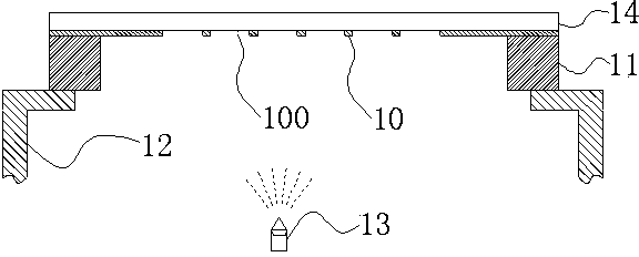
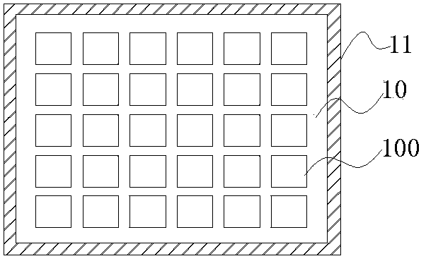
technical field [0001] The invention belongs to the plane display industry, relates to the OLED display industry, and in particular to a method for preparing an OLED mask component. Background technique [0002] Organic Light-Emitting Diode (OLED) is a next-generation display technology. Compared with the currently used Liquid Crystal Display (LCD) display technology, it has a large viewing angle, bright colors, and low power consumption. And other advantages, will gradually replace the current mainstream liquid crystal display technology. [0003] In the fabrication process of the OLED display panel, the deposition of the organic layer will use the mask plate 10, figure 1 Shown is a schematic diagram of evaporating an organic material using a mask plate 10 . Since the mask plate 10 is relatively thin, it will be fixed on the outer frame 11 through related processes before evaporation, figure 2 Shown is a schematic plan view of the mask plate fixed on the outer frame 11 ...

Claims


Application Information

Patent Timeline
IPC IPC(8): C23C14/04C23C14/20
CPCC23C14/042
Inventor 魏志凌赵录军程俊虎
Owner KUN SHAN POWER STENCIL
Why Eureka
Eureka Blog
Learn More