
Water-saving container planted roof

A water-saving and container-based technology, which is applied to roofs, container cultivation, roof coverings, etc., can solve the problems of transportation and transportation to the roof, increase the cost of planting boxes, increase production costs, etc., and achieve good water supply performance , simple structure and simplified installation method

Active Publication Date: 2016-07-06
SHENZHEN INST OF BUILDING RES
View PDF10 Cites 0 Cited by
  • Summary
  • Abstract
  • Description
  • Claims
  • Application Information

AI Technical Summary

Problems solved by technology

Obviously, rainwater has to pass through the soil above the drainage board to reach the drainage board, and then enter the collection box through the drain outlet. Obviously, the soil may also be washed into the collection box by rainwater, causing soil erosion
The rainwater collected in the collection box also needs to pass through the "siphon water supply blanket" to supply water to the soil above the drainage board, the structure is more complicated, which increases the production cost
The movable cone-shaped planting box can be designed to different heights according to needs, so as to meet the requirements of adapting to different soil thicknesses and roofs in different fields, and to facilitate the planting of plants in the factory; The transportation of the top will become extremely difficult, making the original intention of "convenient planting in the factory" defeated, and the manufacturing cost of the planting box will be increased in vain

Method used


Image

  • Water-saving container planted roof
  • Water-saving container planted roof
  • Water-saving container planted roof

Examples


Embodiment 1

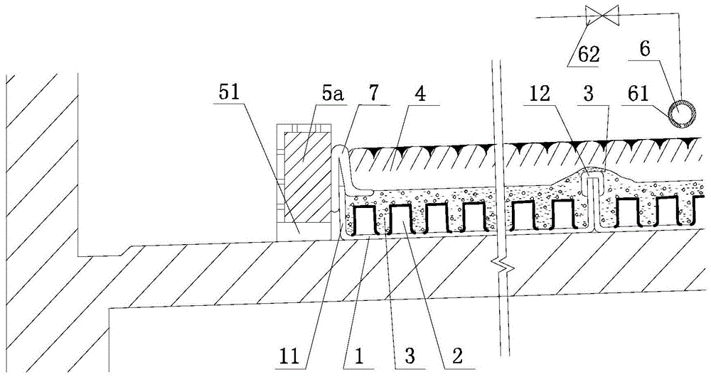
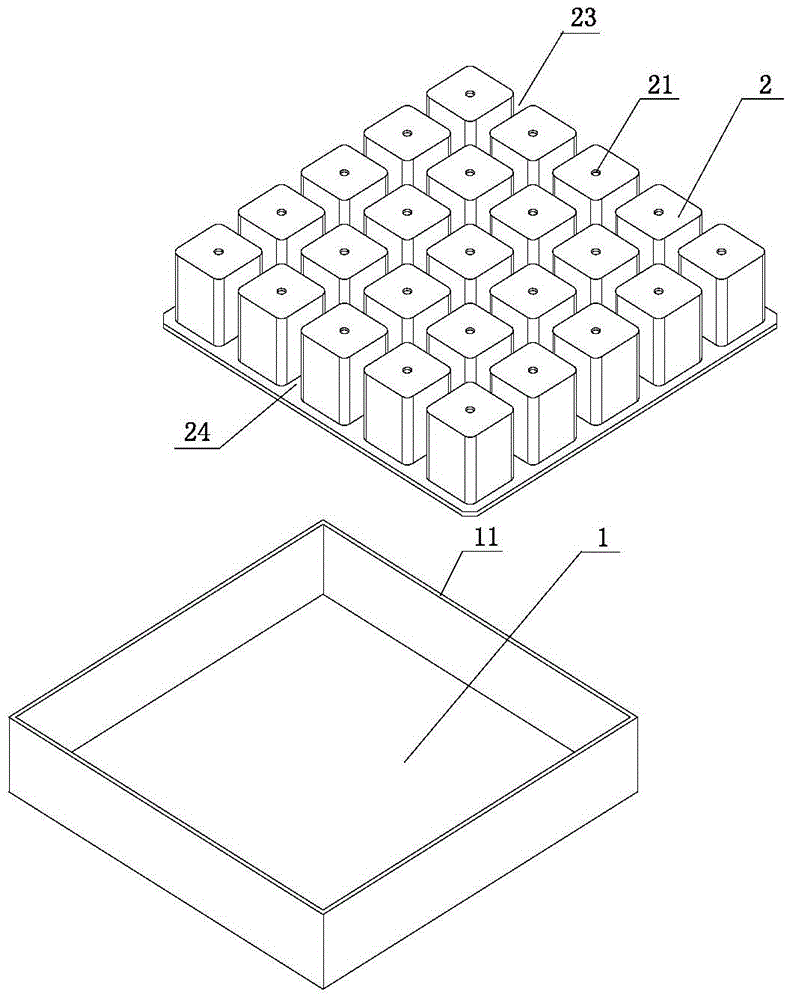
[0033] Example 1, such as figure 1 with figure 2 Shown in:

[0034] In this embodiment, the present invention includes a pool ridge 5a arranged on the building roof 13. In the pool ridge 5a, a plurality of shallow trays 1 arranged closely in a matrix are arranged. The pool ridge 5a and the matrix are arranged The shallow tray 1 constitutes a planting pond; a cylindrical cup plate 2 is provided in the shallow tray 1, and the cylindrical cup plate 2 is composed of a plurality of independent cylindrical cups, and the cup mouth of the cylindrical cup The edges are connected together and arranged in a matrix; the mouth of the cylindrical cup plate 2 is downward, that is, the cylindrical cup plate 2 is inverted in the shallow tray 1; the gap 23 between the independent cylindrical cups A water-absorbing filter material 3 is provided in the two adjacent shallow trays, and a waterproof tape 12 for bonding the two side walls is provided on the upper part of the side walls of the two adjac...

Embodiment 2

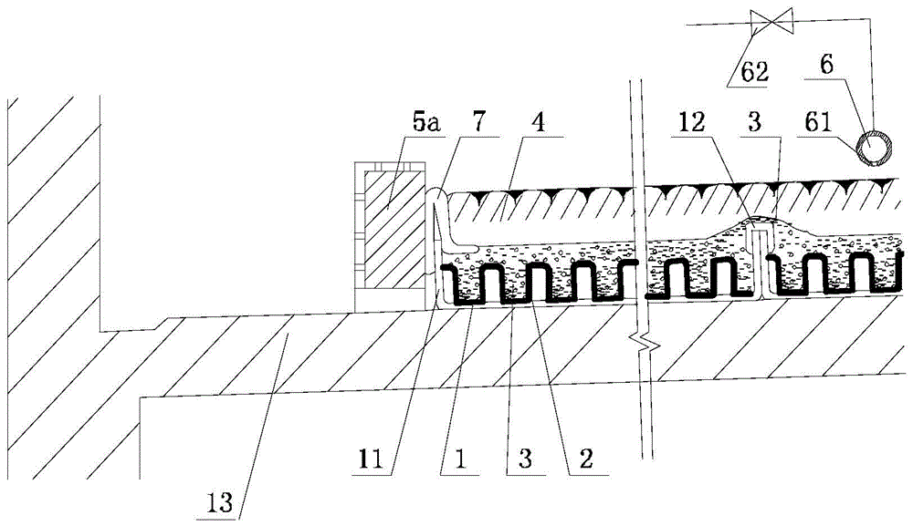
[0054] Example 2, such as image 3 with Figure 4 Shown in:

[0055] In this embodiment, the mouth of the cylindrical cup plate 2 is upward, that is, the cylindrical cup plate 2 is inverted in the shallow tray 1.

[0056] In this embodiment, each cup bottom of the cylindrical cup plate 2 is provided with a first through hole 21 which is actually a water passing hole; a second through hole 22 is actually provided at the center of the junction of the edge 24 of the cup. It is a vent.

[0057] In specific use, if the water-absorbing filter material in the shallow tray is made of aerated concrete particles, the water storage rate can reach 50%. In this embodiment, the space between the cylindrical cup and the cup is a water storage space. In order to obtain a larger water storage space, the cup body of the cylindrical cup can be appropriately reduced, so that the gap between the cylindrical cup and the cup is relatively enlarged. The cylindrical cup with the mouth upward is filled wit...

Embodiment 3

[0059] Example 3, such as Figure 5 Shown in:

[0060] For small building roofs that require greening, the enclosure frame 5b can be made of anticorrosive wood or aluminum profiles to replace the pool ridge. The height of the enclosure frame 5b should be about 80mm higher than the shallow tray 1, and the enclosure frame is set in the shallow tray array On the periphery, the steel rope is used to prevent it from being deformed, and the bottom is not fixed and there is no need to reserve drain holes. A polyester filter cotton 7 should be set between the enclosure frame and the shallow pan. The polyester filter cotton 7 should have a certain width to fully shield the planting soil and prevent the planting soil from falling into the gap between the enclosure frame and the shallow pan.

[0061] In this embodiment, the original roof outside the pool ridge can be covered with a stone path 52 and gravel 53.

[0062] The other parts of this embodiment are exactly the same as the first embod...


PUM


Abstract

The invention provides a water-saving container plating roof and belongs to the technical field of building roof greening. The water-saving container plating roof is characterized by comprising pool ridges arranged on a building roof, wherein a plurality of trays tightly arranged in a matrix mode are arranged in the pool ridges, and the pool ridges and the trays arranged in the matrix mode form a planting pool. Column-shaped cup plates are arranged in the trays and consist of multiple independent column-shaped cups, and the edges of the cup openings of the column-shaped cups are connected together and are arranged in the matrix mode. The cup openings of the column-shaped cup plates are upward or downward. Water absorbing filter materials are arranged in gaps among the independent column-shaped cups or the column-shaped cups, waterproof adhesive tapes for bonding two side walls are arranged at the upper portions of the side walls of every two adjacent trays, and cladding polyester filtration cotton is arranged at the upper portions of the side walls of the trays tightly attached to the pool ridges. Planting soil is arranged in the area surrounded by the pool ridges. Irrigation pipelines are arranged above the planting pool. The water-saving container plating roof is simple in structure, low in manufacture cost and good in water supply and impoundment performance and has reliable seepage preventing performance.

Description

Technical field: [0001] The invention relates to a water-saving container planting roof, which belongs to the technical field of building roof greening. Background technique: [0002] Explanation of technical terms: [0003] Simple roof greening: Planting soil or containers are laid on the roof waterproof layer, and sedum and other low drought-tolerant ground cover plants are planted. [0004] Hybrid roof greening: A greening technology in which a roof greening planting pond is built on the roof waterproof layer, a water storage and drainage layer and a filter layer are set in the pond, planting soil, etc., and ground cover plants or low shrubs and other plants are planted. [0005] Light-weight planting roof: Pave the roof waterproof layer with planting soil or set containers, and plant sedum and other low drought-tolerant ground cover plants, that is, the building roof with simple green roof. [0006] Container planting technology: the technology of laying containers or planting modu...

Claims


Application Information

Patent Timeline
Patent Type & Authority Patents(China)
IPC IPC(8): E04D13/00A01G9/02A01G27/00
CPCY02A30/254Y02B80/32
Inventor 罗刚张炜郭永聪蹇婕张欢
Owner SHENZHEN INST OF BUILDING RES
Learn More