
Lens for LED illumination

A technology of LED lighting and lens, which is applied in the direction of lighting devices, lighting and heating equipment, and parts of lighting devices, etc. It can solve the problems of low effective utilization of light, small lighting range, inconsistent visual range and visual habits, etc.

Active Publication Date: 2015-03-04
NINGBO FRONT WIND ZHENYE LIGHTING
View PDF4 Cites 0 Cited by
  • Summary
  • Abstract
  • Description
  • Claims
  • Application Information

AI Technical Summary

Problems solved by technology

[0002] The emission angle of the light emitted by the lens used for LED lighting is generally about 120 degrees, and the light spot is circular. The lighting range is too large, resulting in low effective utilization of light, and human vision is usually more suitable for the long visual range, so At the same time, it also causes the visual range to be inconsistent with human visual habits. According to the existing technology, an elliptical lens work lamp is disclosed on the website of the State Intellectual Property Office. By setting the elliptical lens, the technical effect of reducing the light spot can be realized reasonably. The elliptical lens with different lens shapes in the two directions of the optical path can realize the technical effect of forming two light spots with different distances in the direction of the polar axis.

Method used


Image

  • Lens for LED illumination
  • Lens for LED illumination
  • Lens for LED illumination

Examples


Embodiment Construction

[0018] The present invention will be further described below in conjunction with the accompanying drawings and specific embodiments.

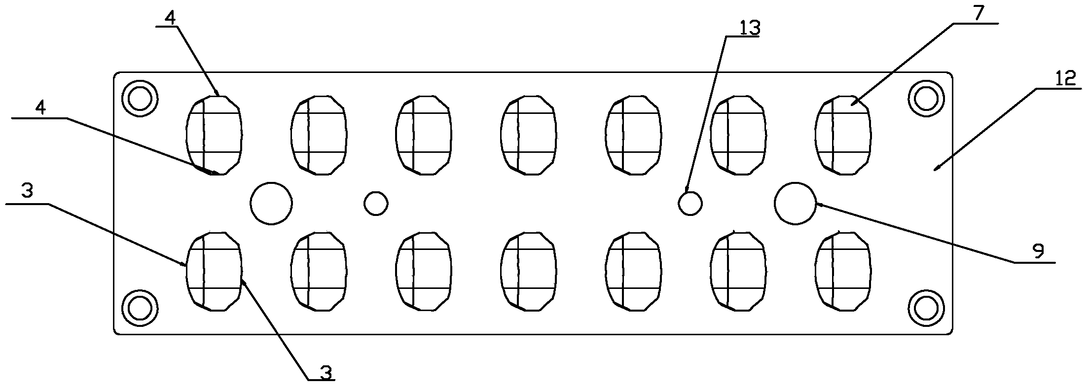
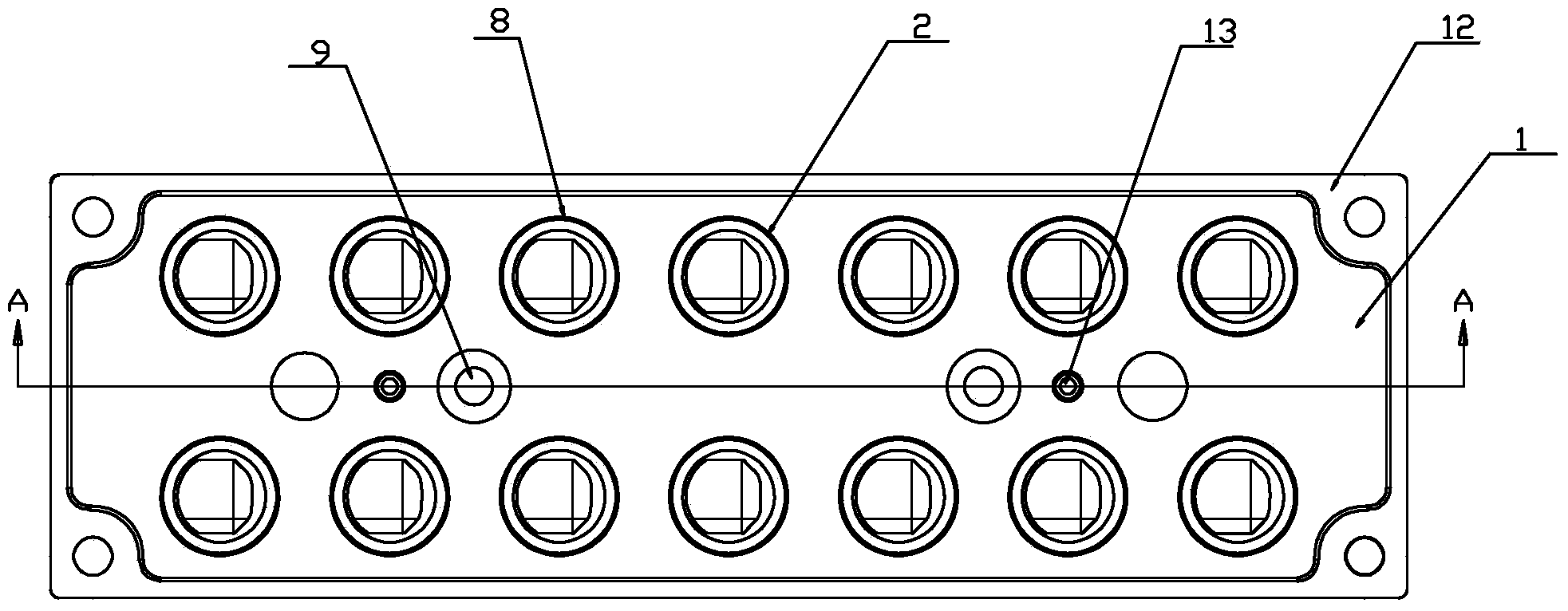
[0019] As shown in the figure, the present invention provides a lens for LED lighting, including a lens platform 1 and a lens body 2 arranged on the lens platform 1, a circuit board 12 is provided at the lower end of the lens platform 1, and the lens The main body 2 includes a light-emitting part 7 and a clamping part 8. The light-emitting part 7 is located at the upper end of the clamping part 8. The clamping part 8 is clamped on the lens platform 1. The light-emitting part 7 includes a The first curved surface 3 on the left and right sides of the part 7 and the second curved surface 4 arranged on the front and rear sides of the light emitting part 7, the outline of the projection of the first curved surface 3 and the second curved surface 4 on the lens platform 1 is an ellipse, and the described The first included angle a formed by the tangen...


PUM

PropertyMeasurementUnit
Depthaaaaaaaaaa
Diameteraaaaaaaaaa
Heightaaaaaaaaaa

Abstract

The invention discloses a lens for an LED illuminating lamp. The lens comprises a lens platform (1) and a lens body (2) arranged on the lens platform (1); a circuit board (12) is arranged at the lower end of the lens platform (1). The lens is characterized in that the lens body (2) comprises a light emitting part (7) and a clamping part (8); the light emitting part (7) is positioned at the upper end of the clamping part (8); the clamping part (8) is clamped on the lens platform (1); the light emitting part (7) comprises first curved surfaces (3) arranged at both the left lateral surface and the right lateral surface of the light emitting part (7) and second curved surfaces arranged at both the front lateral surface and the back lateral surface of the light emitting part (7); the profile of projections of the first curved surfaces (3) and the second curved surfaces (4) on the lens platform (1) is in a shape of an oval; a first included angle alpha formed by tangent lines of the two first curved surfaces (3) is 70 degrees to 80 degrees. The lens for LED illumination, provided by the invention is large in lens emitting angle, large in illuminating range, and high in effective utilization rate of lights.

Description

technical field [0001] The invention relates to a lens, in particular to a lens for LED lighting. Background technique [0002] The emission angle of the light emitted by the lens used for LED lighting is generally about 120 degrees, and the light spot is circular. The lighting range is too large, resulting in low effective utilization of light, and human vision is usually more suitable for the long visual range, so At the same time, it also causes the visual range to be inconsistent with human visual habits. According to the existing technology, an elliptical lens work lamp is disclosed on the website of the State Intellectual Property Office. By setting the elliptical lens, the technical effect of reducing the light spot can be realized reasonably. The elliptical lens with different lens shapes in the two directions of the optical path can realize the technical effect of forming light spots with different distances in the two polar axis directions. Contents of the invent...

Claims


Application Information

Patent Timeline
IPC IPC(8): F21V5/04F21V17/10F21Y101/02
CPCF21V5/04F21V17/10
Inventor 顾振武来亮刘映辉
Owner NINGBO FRONT WIND ZHENYE LIGHTING
Learn More