Remote diagnosis system for measuring instrument and diagnosis method thereof

A technology for remote diagnosis and measurement instruments, applied in the field of remote diagnosis systems, can solve the problems of not considering the combination relationship of measurement instruments, waste of manpower and time, single fault diagnosis, etc., to achieve easy expansion and expansion, increase reusability, diagnosis Efficient effect

Active Publication Date: 2015-03-04
THE 41ST INST OF CHINA ELECTRONICS TECH GRP
View PDF6 Cites 17 Cited by
  • Summary
  • Abstract
  • Description
  • Claims
  • Application Information

AI Technical Summary

Problems solved by technology

In the traditional diagnosis method, the entire measuring instrument group is viewed independently. When a measuring instrument fails, the failure is judged one by one by an independent single instrument. This method does not take into account the combination relationship between various measuring instruments. Because in many cases, when the failure of one measuring instrument will affect other measuring instruments
In the traditional way, the fault diagnosis of remote measuring instruments is limited to a single measuring instrument, but when the measuring instruments are a cluster, there is nothing to do
[0007] For example, in some cases, when the working state of the measuring instrument changes, but the cause of the abnormal state cannot be found through the local diagnostic state, in this case, it is generally due to the poor coordination between the functional modules of the circuit boards It is usually caused by the maintenance personnel coming to the scene and judging the cause of the failure of the measuring instrument through experience. If the maintenance personnel are inexperienced, they may not even be able to solve the problem. In this case, it will cause a huge waste of manpower and time.
[0008] On the other hand, from the

Method used


Image

  • Remote diagnosis system for measuring instrument and diagnosis method thereof
  • Remote diagnosis system for measuring instrument and diagnosis method thereof
  • Remote diagnosis system for measuring instrument and diagnosis method thereof

Examples


Embodiment Construction

[0069] The following will clearly and completely describe the technical solutions in the embodiments of the present invention with reference to the accompanying drawings in the embodiments of the present invention. Obviously, the described embodiments are only some, not all, embodiments of the present invention. Based on the embodiments of the present invention, all other embodiments obtained by persons of ordinary skill in the art without making creative efforts belong to the protection scope of the present invention.

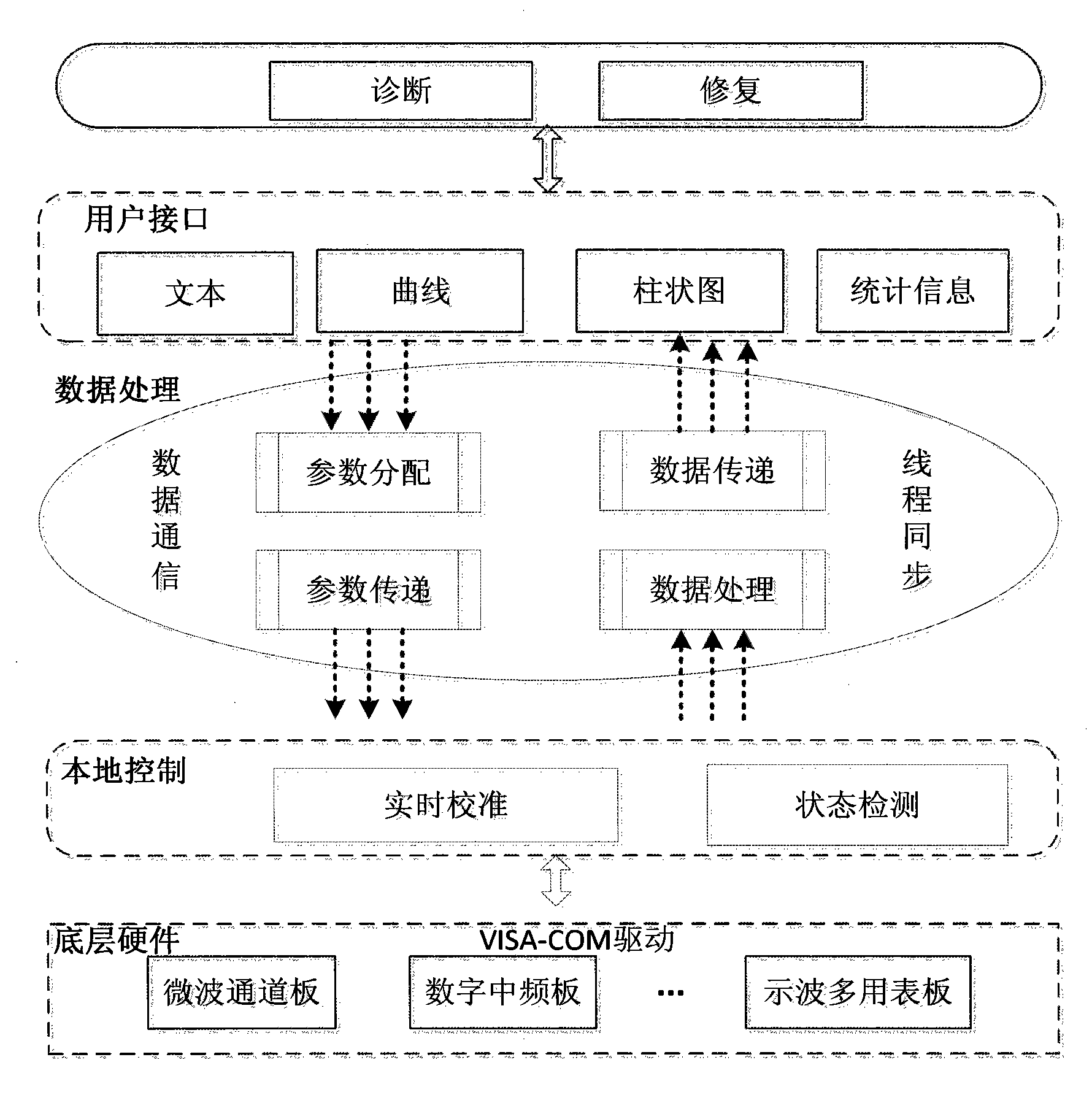
[0070] At present, the traditional diagnosis method is when the measuring instrument breaks down, the engineer repairs it on site or returns the instrument to the manufacturer for repair. This way wastes huge manpower and material cost. The purpose of the present invention is to provide a measuring instrument remote diagnosis system and method with good versatility, realize the diagnosis of the instrument in a local and remote manner, and repair the error.

...


PUM


Abstract

The invention provides a remote diagnosis system for a measuring instrument. The remote diagnosis system is composed of a diagnosis repairing layer, a user interface layer, a data processing layer, a local control layer, a bottom hardware layer. A data acquisition layer of the bottom hardware layer collects diagnosis data; after the diagnosis system receives the collected original data, a fault diagnosis model is invoked to carry out a qualitative and quantitative analysis procedure and an analysis result is stored into the user interface layer; the data processing layer carries out analysis processing on the diagnosis data and the data are converted into ones in parametric formats like a text, a histogram, and statistical information and the like; the diagnosis result is displayed by the user interface layer; and for the repairable fault, the remote diagnosis repairing module sends a remote control command, hardware and software states are set based on the parsing transmission of the remote control command, and the fault is repaired.

Description

technical field [0001] The invention relates to the field of electronic measuring instruments, in particular to a remote diagnosis system and a diagnosis method for measuring instruments. Background technique [0002] With the development of measurement technology, the functions of measuring instruments are becoming more and more complex, integrating various advanced electronic technologies, and measuring instruments are characterized by dispersion, movement and complex functions, which makes the fault diagnosis and state detection of measuring instruments problematic. Increasingly prominent, the task is becoming more and more difficult. In the traditional way, when the measuring instrument breaks down, it is necessary to rely on technicians to communicate on-site to realize the fault diagnosis of the measuring instrument. This method requires a lot of manpower, material resources and time costs for both users and technicians. [0003] In the existing methods, for example, ...

Claims


Application Information

Patent Timeline
IPC IPC(8): G01R31/00
Inventor 李伟白轶荣杜念文刘宝东丁建岽
Owner THE 41ST INST OF CHINA ELECTRONICS TECH GRP
Why Eureka
Try Eureka