Digital peak current control device
A peak current control, digital-to-analog conversion circuit technology, applied in the output power conversion device, electrical components and other directions, can solve the problems of difficult to achieve digital power supply, high current sampling requirements, difficult to achieve, etc., to achieve flexible implementation methods, Low cost and high reliability
- Summary
- Abstract
- Description
- Claims
- Application Information
AI Technical Summary
Problems solved by technology
Method used
Image
Examples
Embodiment 1
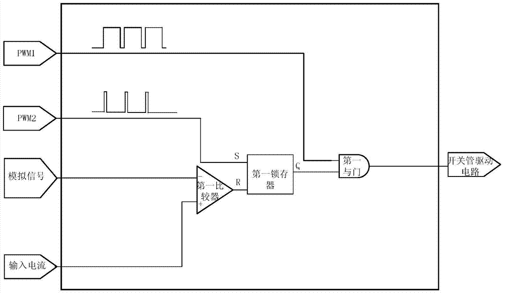
[0031] Such as figure 1 As shown, the digital peak current control device of this embodiment can be applied to switching power supplies with only one switching tube, such as buck converters, boost converters, single-ended forward converters, and single-ended flyback converters. Embodiments are applicable in discontinuous mode. It includes a sampling circuit, a given circuit, a single-chip microcomputer, a digital-to-analog conversion circuit (D / A), a rectification circuit and a peak current control circuit. The peak current control circuit includes a first comparator, a first latch and a first AND gate. The single-chip microcomputer has a first output terminal for outputting a first PWM signal (PWM1) and a second output terminal for outputting a second PWM signal (PWM2). Wherein, the pulse width of the first PWM signal is greater than the pulse width of the second PWM signal, that is, the first PWM signal defines the maximum width of the pulse.
[0032] The sampling circuit...
Embodiment 2
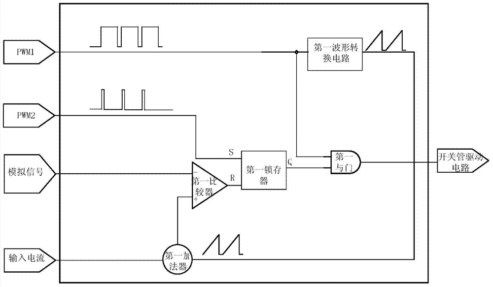
[0040] Such as figure 2 As shown, the difference between this embodiment and Embodiment 1 is that the peak current control circuit further includes a first waveform conversion circuit and a first adder for converting a rectangular wave into a triangular wave. Specifically, the output terminal of the rectification circuit is connected to the non-inverting input terminal of the first comparator through the first adder, and the output terminal of the first waveform conversion circuit is also connected to the first comparator through the first adder. The non-inverting input terminal of the single-chip microcomputer is also connected with the input terminal of the first waveform conversion circuit.
[0041] This embodiment is also applicable to a switching power supply with only one switching tube, such as a buck converter, a boost converter, a single-ended forward converter, and a single-ended flyback converter, but this embodiment is applicable to a continuous mode.
[0042] When...
Embodiment 3
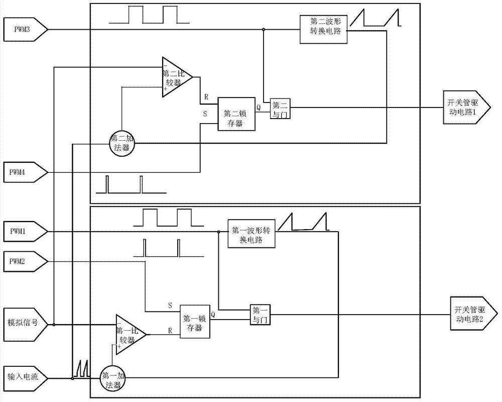
[0044] Such as image 3 As shown, the difference between the present embodiment and the second embodiment is that an adder, a comparator, a latch and a waveform conversion circuit are added. Therefore, this embodiment is suitable for switching power supplies with two switching tubes, such as half-bridge converters and push-pull converters.
[0045] Specifically, the peak current control circuit further includes a second adder, a second latch, a second comparator, a second AND gate, and a second waveform conversion circuit for converting a rectangular wave into a triangular wave. The single-chip microcomputer also has a third output terminal for outputting a third PWM signal (PWM3) and a fourth output terminal for outputting a fourth PWM signal (PWM4). The output end of the rectification circuit is connected to the non-inverting input end of the second comparator through the second adder, and the output end of the second waveform conversion circuit is also connected to the non...
PUM
 Abstract
Description
Claims
Application Information
 - R&D
- Intellectual Property
- Life Sciences
- Materials
- Tech Scout
- Unparalleled Data Quality
- Higher Quality Content
- 60% Fewer Hallucinations
Browse by: Latest US Patents, China's latest patents, Technical Efficacy Thesaurus, Application Domain, Technology Topic, Popular Technical Reports.
© 2025 PatSnap. All rights reserved.Legal|Privacy policy|Modern Slavery Act Transparency Statement|Sitemap|About US| Contact US: help@patsnap.com


