
Intelligent detection device imaging system and imaging method for vision technology

A technology of intelligent detection and vision technology, applied in the field of image processing, can solve the problems of high imaging cost of intelligent detection device, defects of linear structure data fusion two-dimensional image speed, accuracy and degree of intelligence, etc.

Inactive Publication Date: 2020-10-27
SHANDONG UNIV OF SCI & TECH
View PDF0 Cites 2 Cited by
  • Summary
  • Abstract
  • Description
  • Claims
  • Application Information

AI Technical Summary

Problems solved by technology

[0007] Through the above analysis, the problems and defects of the existing technology are: the imaging cost of the intelligent detection device is high, and the speed, accuracy and intelligence of the linear structure data fusion and stitching into two-dimensional images have defects
[0008] The difficulty in solving the above problems and defects is as follows: With the continuous improvement of detection accuracy and accuracy, the resolution of the visual acquisition device adopted is continuously improved. For example, the mainstream line scan camera has reached 8K or even higher, and the area array camera has generally reached Tens of millions of pixels, which not only puts forward high requirements on the storage and computing capabilities of the processing device, but also requires higher spatial registration accuracy

Method used


Image

  • Intelligent detection device imaging system and imaging method for vision technology
  • Intelligent detection device imaging system and imaging method for vision technology

Examples


Embodiment

[0055] Image acquisition subsystem. The invention intends to use a label rotating detection device for regular objects. Since the detection speeds of labels on different product lines are different, they are all required to match the detection speeds of other series on the filling line. The speed and clarity of photographing are the key, and the design of the camera and photographing mechanism is particularly important. In the surface scanning mode, the regular target moves forward in a straight line without rotation, but generally multiple cameras are required to work at the same time, and one target is photographed from multiple angles to form several images containing repeated areas, which are finally transmitted to the computer for preprocessing, Fusion, understanding and recognition. The line scan method only needs one camera and the corresponding light source, and the regular target must still maintain a constant speed rotation state when moving forward at a constant sp...


PUM


Abstract

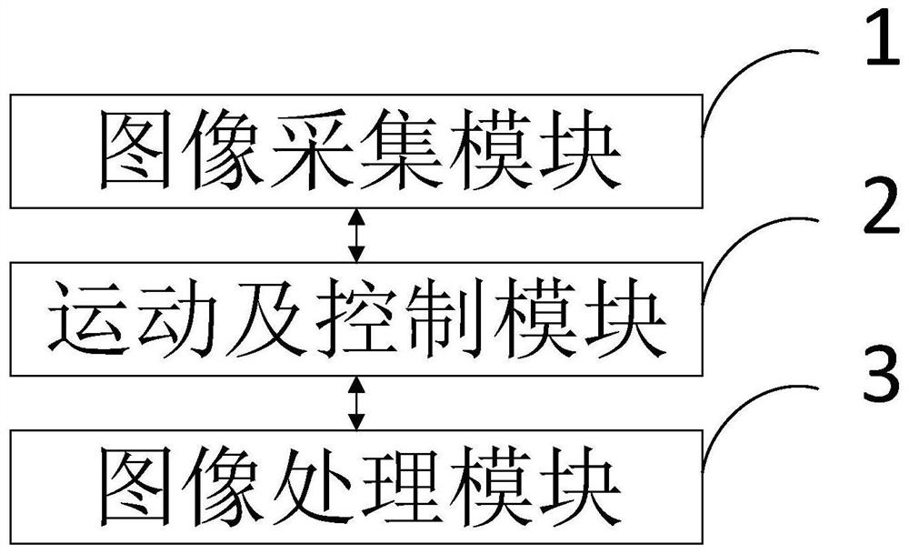
The invention belongs to the technical field of image processing, and discloses an intelligent detection device imaging system and imaging method for the visual technology, and the system comprises: an image collection module which obtains an original image with the uniform chromaticity and gray scale through employing a line scanning camera and a surface scanning camera of an embedded architecture; the motion and control module that performs light source control and regular target object self-rotation by utilizing a uniform-speed self-rotation and uniform-speed advancing device; and the imageprocessing module that processes the acquired image data. According to the invention, a geometric algebraic algorithm is adopted, rapid feature extraction and feature matching of the scanned image are achieved, the speed can be guaranteed, feature points can be increased, and the feature points suitable for imaging of the rotary line scanning camera are obtained; according to the invention, the O-RANSAC algorithm-based image registration and fusion technology is adopted, so that the speed and precision of image fusion and registration are improved. According to the invention, the splicing transverse pixel error is controlled within 5, and the vertical pixel error is 0.

Description

technical field [0001] The invention belongs to the technical field of image processing, and in particular relates to an imaging system and an imaging method of an intelligent detection device for visual technology. Background technique [0002] At present, computer vision-based detection is a hot technology developed in recent years. Especially with the widespread application of AI+ big data, its application scenarios have achieved unprecedented breakthroughs, and the subsequent market prospects are also extremely broad. This kind of equipment uses the means of integration of light, machine, electricity and computer control to make the machine have the function of intelligent vision. Introducing computer vision into the detection field can realize online high-precision and high-speed measurement in many occasions. In the early stage of development, it was mainly concentrated in Europe, America and Japan. With the transfer of the global manufacturing center to China, the C...

Claims


Application Information

Patent Timeline
IPC IPC(8): G06T7/33G06K9/46G06K9/62H04N5/232
CPCG06T7/33G06V10/462G06V10/751H04N23/695G06F18/253
Inventor 安新军祝长生臧祥腾施陈博张淳
Owner SHANDONG UNIV OF SCI & TECH
Learn More