Supercharge Your Innovation With Domain-Expert AI Agents!

Injection device

An injection cylinder and injection molding technology, applied in the field of injection devices, can solve the problems of increased number of components, large-scale, complicated structure of injection devices, etc., and achieve the effect of high injection speed and high injection pressure

Inactive Publication Date: 2016-02-17
TOYOTA IND CORP
View PDF6 Cites 0 Cited by
  • Summary
  • Abstract
  • Description
  • Claims
  • Application Information

AI Technical Summary

Problems solved by technology

Therefore, the number of parts increases, and the structure of the injection device is complicated and enlarged

Method used


Image

  • Injection device

Examples


Embodiment Construction

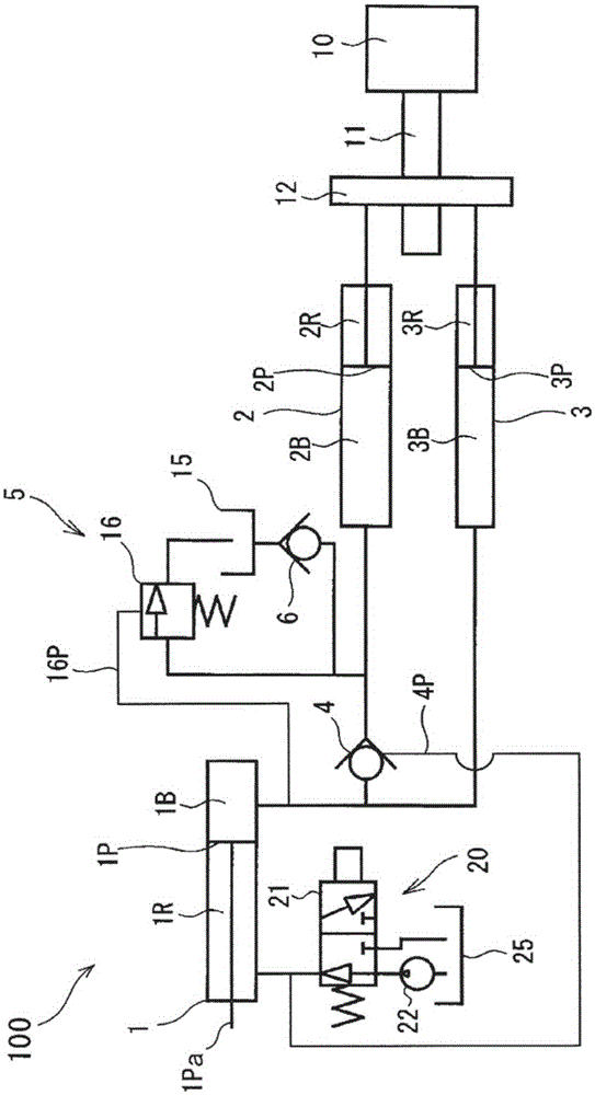
[0009] Hereinafter, the injection device according to the embodiment of the present invention will be described.

[0010] A die casting machine as an injection device is a device that injects and fills a molten metal material (for example, aluminum) as a molding material into a cavity formed by a fixed mold and a movable mold constituting a mold. The molding material injected into the mold is taken out after solidification, thereby becoming a desired molded product. Reference figure 1 , The die casting machine 100 includes an injection cylinder 1. The injection cylinder 1 is a component that drives an injection plunger that extrudes a metal material supplied into an injection sleeve communicating with a mold cavity into the mold cavity. The injection plunger is connected to the tip of the piston rod 1Pa of the piston 1P of the injection cylinder 1. The injection cylinder 1 is connected with a booster cylinder 2 as a first cylinder and a booster cylinder 3 as a second cylinder ...


PUM


Abstract

The present invention relates to injection devices. In the injection device (100), a speed-up cylinder (2) and a booster cylinder (3) driving an injection cylinder (1) connected to an injection plunger are connected in parallel to the injection cylinder (1). The piston (2P) of the speed increasing cylinder (2) and the piston (3P) of the boosting cylinder (3) are synchronously driven by the motor (10), the ball screw (11) and the nut (12). A hydraulic control check valve (4) and a flow adjustment circuit (5) are arranged between the bottom chamber (1B) of the injection cylinder (1) and the bottom chamber (2B) of the speed-increasing cylinder (2). Thus, the injection device (100) drives the injection cylinder (1) at high speed by both the speed-increasing cylinder (2) and the booster cylinder (3) with the driving force of a single motor (10), and only uses the booster cylinder ( 3) Drive the injection cylinder (1) under high pressure.

Description

Technical field [0001] The invention relates to an injection device. Background technique [0002] As an apparatus for molding a desired product by injecting and filling a molding material into a mold, an injection apparatus is known. Furthermore, in recent injection devices, for example, as in the injection device of Patent Document 1, an electric motor is used to apply an operating force to the injection cylinder. The injection device of Patent Document 1 includes: an injection cylinder device that operates an injection plunger that injects a molding material into a mold; and a switching cylinder device that supplies hydraulic fluid to the injection cylinder device. Furthermore, in the injection device of Patent Document 1, when supplying hydraulic oil to the injection cylinder, an electric motor is used as a driving source of the switching piston of the switching cylinder device. Therefore, in the injection device of Patent Document 1, the operation of the switching piston o...

Claims


Application Information

Patent Timeline
Patent Type & Authority Patents(China)
IPC IPC(8): B22D17/32B29C45/53
CPCB22D17/2015B22D17/32B29C45/531B29C45/82B22D17/10B22D17/203B22D17/2038B22D21/007
Inventor 山口和幸舟桥一起
Owner TOYOTA IND CORP
Features
  • R&D
  • Intellectual Property
  • Life Sciences
  • Materials
  • Tech Scout
  • Unparalleled Data Quality
  • Higher Quality Content
  • 60% Fewer Hallucinations
Learn More